Swift split charge relay and habitation relay location help

If I temporarily jump 13.1v between red and brown feeds the volt meter works again for engine battery on the main control panel and I assume the step will retract and frdige work again. So just need to know where the large red wire is fed from in vehicle? Had checked all the battery large fuses when I changed the engine battery last week.
 
Last edited:
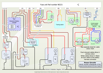
The Nordelectronica wiring is shown in the 2009 section of sargentltd.co.uk/tech-support/artical/swift-group-schematics/25
The large red wire is the supply from the starter battery through a 40amp fuse .
 
The Nordelectronica wiring is shown in the 2009 section of sargentltd.co.uk/tech-support/artical/swift-group-schematics/25
The large red wire is the supply from the starter battery through a 40amp fuse .
OK that's what I though. I will trace the wiring and see where the issue is. Its definitely not the fuse at the battery but will check again and trace the cable.
 
Not sure if this has already been said, I have seen others install a cut-off relay by the leisure battery so you do not have to do any modifications to the original van control panel. This way the step still retracts on ignition, the fridge still changes over to engine and the B2B does all the charging. Diagram below see if this is of any help to anyone. If the relay fails to energise on ignition the buzzer will sound
Bypass relay.jpg

Subscribers  do not see these advertisements

 
Ok so I have done some further tests.
All large fuses near battery are in tact under passenger floor in engine battery comp
All large fuses in engine fuse box in tact
in dashboard fuse box 40 amp fuse is in tact.
In drivers B Pilar at the connector between fiat and motorhome there is 0v. Also Ov on NE222 brown wire.

I have no idea where this is fed from. I could run a new wire and tap into engine battery at B2B (25mm cable) but would really prefer to fix the issue.

Anything I have missed?
 
Not sure if this has already been said, I have seen others install a cut-off relay by the leisure battery so you do not have to do any modifications to the original van control panel. This way the step still retracts on ignition, the fridge still changes over to engine and the B2B does all the charging. Diagram below see if this is of any help to anyone. If the relay fails to energise on ignition the buzzer will sound
View attachment 501304
Yes I plan to do this once I fix the feed issue.
 
In drivers B Pilar at the connector between fiat and motorhome there is 0v. Also Ov on NE222 brown wire.

On my X250 Fiat van, there is a plastic rectangular duct beneath the passenger/drivers seat. This takes a +ve cable from the starter battery multi-terminal, down the outer side of the passenger seat (below floor level in duct) and across under the front seats. If you remove the drivers plastic footwell, you should see this cable and it's connection to the terminal block on the B pillar.

Suggest you initially run a temporary cable from the 12v + starter battery terminal to the B pillar and check voltage.

Edit, you may find the pics in #1 of this thread helpful:

 
Last edited:
On my X250 Fiat van, there is a plastic rectangular duct beneath the passenger/drivers seat. This takes a +ve cable from the starter battery multi-terminal, down the outer side of the passenger seat (below floor level in duct) and across under the front seats. If you remove the drivers plastic footwell, you should see this cable and it's connection to the terminal block on the B pillar.

Suggest you initially run a temporary cable from the 12v + starter battery terminal to the B pillar and check voltage.

Edit, you may find the pics in #1 of this thread helpful:

Ok thanks for help. I’ve rechecked and found a 50 amp blown fuse on battery block. Have replaced it temporarily with a 30 amp One until I order up a 50 amp one. Voltmeter now works on main panel and fridge works on 12v. However step is not auto retracting on ignition. It works fine on manual switch. Would like to solve this issue before disabling split charger with a bypass relay on the leisure battery connection as discussed a above.
 
Does anyone have a wiring diagram with fuse feeds for the NE222? The main brown wire is 13.1v (leisure battery) and red one is 0v with ignition off and on.
I assume the large red wire should be vehicle battery permanent live. trying to find where this is supplied from to check fuse etc.
So I fixed the feed issue (it was a fuse after all)

voltmeter now works for ne222 display panel. However the ignition feed is not working as step does not retract and fridge now shows error if you switch to 12v and engine running.

I believe pin 7 of jp3 should be d+ from ignition but mine is not going live. Anyone know where this feed comes from and if a fuse could be blown? Everything else is working.

Subscribers  do not see these advertisements

 
I am really struggling to find the D+ ignition feed to my NE221 board. The swift manual suggests its on J2 but I do not have J1, J2 or J3 on the board I have (it does state NE221.1 on the board see pic below). I have B1, B2 etc for the battery feeds. Someone said try pin 7 of JP3 but this is at 9v constant. I think I must be missing something really obvious here. I would also like to locate CO36L1A (fiat connector) so I can check here for D+ feed - anyone know where it is ?
 

Attachments

  • NE221.png
    NE221.png
    176.8 KB · Views: 114
  • Ne221dot1.jpeg
    Ne221dot1.jpeg
    87.1 KB · Views: 98
Last edited:
Have you checked JP4 which is the plug into the NE221 from the fiat CO36L1A connector to check if it has D+ voltage, the other possibility is that a voltage sensing relay is used inside the NE221 instead of a D+ relay
 
I have checked pin 6 of JP4 and even if I put 12v on it from a good source (leisure or engine battery) with engine running step does not close. I am thinking this is an issue with my board now. Have asked Apuljack engineering for their views
 
Have you checked all the earth connections at the step and any others at the NE221 and elsewhere as the D+ could operate a relay that completes an earth return on the step circuit which is powered by the leisure battery.

Subscribers  do not see these advertisements

 
yes have checked all earth connections. Its not just the step not retracting. The fridge does not switch to 12v and habitation relay does not cut out (so lights/water pump work etc). Its like the D+ feed not working but when I put 12v on it does not work so suspect it must be the circuit board ?
 
Ok it looks like it needs Apuljack to check it out , they have been very good when I have used them in the past. (out of interest, the terminals being marked B1 B2 B3 indicate a higher amperage up-rated unit)
 
Sorry to bring this back up but while the thread is here I’ll try get some information from it if ok being a member im really stuck
I have the Nord Ne221 fuse board with this split charge relay also I’m wanting to disable with the Victron b2b I have fitted but snipping these resistor legs I’m told I need to do
snip one end,
whichever end is most accessible. Try to do
it halfway along the silver wire. Lift the resistor slightly, and slide a bit of sleeving over it.
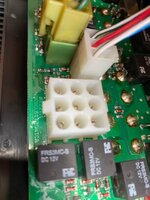
I have located these spade pins that pass threw the board from the relay but can’t see any wire or a resistor on this relay only the other relay however I’ve got 2 relays side by side one at the b1 and the other b2 the one I’m told is the split charge relay is b1 but nothing is on the other side only spade legs
The other relay tho as a resistor
and some wires soldered to it
So is this the one I want and to cut this leg and place a sleeve over it incase someday it may need to solder back if I sell ?
Any help be great
I don’t want to cut wrong
 

Attachments

  • A7397F3B-B2DA-4B92-811B-EC4F4E360A34.jpeg
    A7397F3B-B2DA-4B92-811B-EC4F4E360A34.jpeg
    652.8 KB · Views: 65
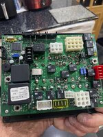
The split charge relay is the one that is squarely between the B1 and B2 terminals. The other relay next to the B2 terminal, is probably the one that cuts off all the hab circuits when the engine is running. Or possibly the fridge relay.

Are you sure the instructions relate to this system? It looks to me like all the resistors are 'surface mount' types, soldered down onto the board without wires. The instructions sound like they are for the older type of resistors with a wire coming out of each end. There's a couple of those over on the right of the board, but I'm not convinced they are the ones you want.

I would contact Delta Conversions, who supply Nordelettronica units and spares, and also repair them, they will probably tell you how to disable the split charge relay. On some of them there was a jumper that needed to be either connected or disconnected, can't remember which.
If you do find out, it would be great if you posted how they said to do it.
 
Last edited:
The split charge relay is the one that is squarely between the B1 and B2 terminals. The other relay next to the B2 terminal, is probably the one that cuts off all the hab circuits when the engine is running. Or possibly the fridge relay.

Are you sure the instructions relate to this system? It looks to me like all the resistors are 'surface mount' types, soldered down onto the board without wires. The instructions sound like they are for the older type of resistors with a wire coming out of each end. There's a couple of those over on the right of the board, but I'm not convinced they are the ones you want.

I would contact Delta Conversions, who supply Nordelettronica units and spares, and also repair them, they will probably tell you how to disable the split charge relay. On some of them there was a jumper that needed to be either connected or disconnected, can't remember which.
If you do find out, it would be great if you posted how they said to do it.
Thank buddy
Yes I’m thinking the information is for another system
I have spoke with Paul at delta who on 2 occasions said to me and others you can’t fit a b2b with the nord system .
But.. Apuljack said that’s wrong and you can lol they said they would email me over the information how to do it. Or I could send it in they would take care of it
This is actually all new from them but at the time I wasn’t interested in a b2b so this relay wasn’t altered
But on the phone yesterday he said I can actually do it myself cutting a leg on a resistor but would email it all over
No email came ….. I will report back definitely

Subscribers  do not see these advertisements

 
Thank buddy
Yes I’m thinking the information is for another system
I have spoke with Paul at delta who on 2 occasions said to me and others you can’t fit a b2b with the nord system .
But.. Apuljack said that’s wrong and you can lol they said they would email me over the information how to do it. Or I could send it in they would take care of it
This is actually all new from them but at the time I wasn’t interested in a b2b so this relay wasn’t altered
But on the phone yesterday he said I can actually do it myself cutting a leg on a resistor but would email it all over
No email came ….. I will report back definitely
I was on the phone yesterday to Paul who I know at delta
When I bought my motorhome I had issues with wiring and the fuse board so I was in contact with both parties for weeks ,, both are amazing and offer so much support
Because I’ve purchased from apuljack recently he said on the phone yesterday we charge £60 to disable the output to the relay itself not the actual relay taken out
But when I mentioned the above information he said yes you got it that’s all that is needed or at any point you need it again just get someone handy with the gun 👍 I will ring them today on my break see when this email is coming on how to do it
This definitely needs posting because I have not seen anyone say yet just how they did it
 
I have said in a couple of threads that I have just removed the relay workings. This is obviously a no going back approach but I don’t intend to. I have done this on two Nord boards now with no problems.
 
I have said in a couple of threads that I have just removed the relay workings. This is obviously a no going back approach but I don’t intend to. I have done this on two Nord boards now with no problems.
Can you show how please because I’m still waiting on emails on the approach
At the moment all I’m getting is send it in we charge 1 hours fee😂
I don’t want to ever use it again either but apparently most nord fuse boards are different especially the ne221 that connects to the ne222
 
Can you show how please because I’m still waiting on emails on the approach
At the moment all I’m getting is send it in we charge 1 hours fee😂
I don’t want to ever use it again either but apparently most nord fuse boards are different especially the ne221 that connects to the ne222
Can I just say they did say DO NOT CUT THE BACK off the relay and take it all out this will cause issues
We disable the output from the relay, not the relay itself, so all the otherfunctions that are related to the split charge relay will still function. If they didn’t, there would be problems! cutting into the relay on this board causes problems
 
I have said in a couple of threads that I have just removed the relay workings. This is obviously a no going back approach but I don’t intend to. I have done this on two Nord boards now with no problems.
Is this what you did mate cut into the relay back and cut the insides out ? I’m guessing that’s all you can do and it’s what they do
That will disable the output
But …. What nord fuse boards did you do it to ?

Subscribers  do not see these advertisements

 
Is this what you did mate cut into the relay back and cut the insides out ? I’m guessing that’s all you can do and it’s what they do
That will disable the output
But …. What nord fuse boards did you do it to ?
I’m home again at the weekend and will tell you the two Nord boards I have done this to. Basically it’s butchery, remove relay cover, cut away all the workings and replace cover.
 
The other one I think is the NE356
 
Hi I have actually done this on my NE148 board. The relays are soldered and failing to remove the relay I took a pair of pliers and disabled it, or to put it another way, I ripped the casing off and pulled the innards out! Make sure you get the correct relay though! I cannot remember how I figured which one to go at. There has been chatter about removing a jumper or a solder connection on the pcb but these were not options on my board. The NE 221 is newer I would guess so may have an easier option to disable, Delta conversions hopefully ca

Is this the same board here on the pic like the one you took the back off the relay you mentioned buddy
 
This one I meant to comment on sorry is this yours you took the insides out buddy ? I’m still having issues with mine I don’t want to touch just yet incase I do a lot of damage . But if this is what yours looks like so does mine

Subscribers  do not see these advertisements


Join us or log in to post a reply.

To join in you must be a member of MotorhomeFun

Join MotorhomeFun

Join us, it quick and easy!

Log in

Already a member? Log in here.

Latest journal entries

Back
Top