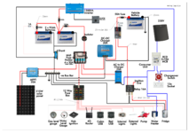
Please critique my wiring diagram.

Can I ask you why you would think an invertor can replace a Ac-Dc charger?
Not 'replace' - I have a Victron Multiplus which is also a charger, and I'd assumed all the Victron inverters did this. However, turns out that the OP is re-using an old inverter
Victron gear is used by some of the best installers across the globe both professionally and self builders , what basis do you use to say it’s not good and only supports their own batteries?
Not sure I said it wasnt 'good' - did I? On mobile at the moment. However, the charger on the multiplus only has one Lithium profile, which is for Victron's battery. Not good. But...
I have Victron gear and it works with my non Victron batteries.
Yes, it does charge my cheap Chinese battery, and hasn't blown anything up yet.

The problem with Victron kit is that people buy it for the name. Seeing a wiring diagram with 3 separate Victron boxes on it is a red flag, to me anyway.
 
Not sure I said it wasnt 'good' - did I? On mobile at the moment. However, the charger on the multiplus only has one Lithium profile, which is for Victron's battery. Not good. But...
That's odd because the much cheaper stand alone Victron IP22 charger I have allows me to customise any of the standard profiles. I have not needed to change the standard lithium profile because it is within the parameters for my lithium batteries
 
Not 'replace' - I have a Victron Multiplus which is also a charger, and I'd assumed all the Victron inverters did this. However, turns out that the OP is re-using an old inverter

Not sure I said it wasnt 'good' - did I? On mobile at the moment. However, the charger on the multiplus only has one Lithium profile, which is for Victron's battery. Not good. But...

Yes, it does charge my cheap Chinese battery, and hasn't blown anything up yet.

The problem with Victron kit is that people buy it for the name. Seeing a wiring diagram with 3 separate Victron boxes on it is a red flag, to me anyway.
I don’t think you need to take things literary, obviously on one of their diagrams they are not going to show someone else’s battery, a battery is a battery, and Lithium batteries are basically the same they nearly all have a BMS that will protect it from chargers.
 
Thanks for all the helpful comments. I've updated the drawing to take them on board.
 

Attachments

  • wiring layout.png
    wiring layout.png
    667.2 KB · Views: 105
You may need to look again at your fuse sizes between the leisure batteries, and also to the inverter?

Your batteries will have an charge / discharge rate - usually listed as a C rate in specs. Keeping below that is kinder to the batteries. Too heavy a discharge rate will shorten the life of the batteries, potentially damaging them if the internal plates can't keep up.

Fuses and cable size should be set accordingly. Between the batteries you have a 200A fuse, may be high?

The inverter you have shown is 1200VA i.e potential 1000W output @ 230V 25deg C, but can allow brief peak of 2200W to deal with initial startup loads. At 2200W, ignoring inefficiencies of the inverter itself, that is over 180A at 12V. You only have a 150A fuse shown. But can your batteries together even support the discharge rate for the normal loading of 1000W (about 83A plus inverter inefficiency)?

Your cable sizes need to support the peak load, allowing for voltage drops, which depends on their length. Some may be a bit small, even to the habitation systems of USB, etc? 12V planet have a good calculator.

To clarify comments above on Victron components, most of their chargers and controllers will have profiles that may match their own batteries. But if you have the smart components which are bluetooth easy to get the various apps for phone to set your own custom preferences and profiles to suit your own batteries and systems if the Victron defaults don't match. I have a mix of Victron and Sterling stuff in my van which has been fine to cross match. Also the inverter systems Victron offer standalone inverter and chargers, and some integrated inverter/chargers the latter putting all your eggs in one basket which won't suit everyone and for which there may not always be the physical space for the larger box.

Subscribers  do not see these advertisements

 
Last edited:
You have a 100 amp fuse direct from the battery then you have an 80 amp Maxi fuse in the Maxi/Midi fuse box you don't need the 80 amp one in the fuse box.
 
I've got a bad feeling about your consumer unit wiring. What's the changeover switch for? The inverter has (or should have) relays for changeover. You also need to put the RCCBs between the 230V output on the inverter and the sockets
You haven't addressed the comments made by EML, above.
 
  • Like
Reactions: EML
You haven't addressed the comments made by EML, above.
He has, needs to have the swich over, EML confused a Phoenix inverter for a multiplus bi directional.

Kannon Fodda, that fuse is plenty for the 1200va inverter se my comment early in the tread. A anl fuse will blow at 1.6 times the nominal current, so a surge of 2kva will be fine. I would stay with the 150A on 25mm2. If it blows, it will not be the surge. I use a 150A on a 2000va and loaded to 14-1500w sustained load in excess of 30-40 mins. I have a 180A spare in the box, never need.
 
He has, needs to have the swich over, EML confused a Phoenix inverter for a multiplus bi directional.
I think you might have mis-read Revolvor's comment. With the changeover switch on the right, the sockets are driven directly from the inverter, with no circuit protection. A small child sticking a screwdriver in the socket would probably notice the lack of an RCD/RCCB. Of course, if nicknoxx doesn't have a small child, that may not be an issue.

At the very least, nicknoxx has to move the changeover switch. A much better solution is to get a multifunction inverter instead, like the multiplus. He could then throw away the manual changeover switch, the AC/DC charger, and the cabling from the charger to the battery. He would then have EHU direct to the inverter via a switch on the CU, and a single high-voltage line out of the inverter, through the RCCB on the CU, direct to the sockets. No changeover switch needed; it's automatic.

Subscribers  do not see these advertisements

 
Shunt is wrong. Shunt alone connects to the battery negative. Your inverter and other hab stuff must be on the outlet side of the Shunt. Connect inverter neg to the neg busbar.
God I love hearing experts talk. I understand about 9 words in that paragraph. Not taking the pee, just envious!😄
 
I think you might have mis-read Revolvor's comment. With the changeover switch on the right, the sockets are driven directly from the inverter, with no circuit protection. A small child sticking a screwdriver in the socket would probably notice the lack of an RCD/RCCB. Of course, if nicknoxx doesn't have a small child, that may not be an issue.

At the very least, nicknoxx has to move the changeover switch. A much better solution is to get a multifunction inverter instead, like the multiplus. He could then throw away the manual changeover switch, the AC/DC charger, and the cabling from the charger to the battery. He would then have EHU direct to the inverter via a switch on the CU, and a single high-voltage line out of the inverter, through the RCCB on the CU, direct to the sockets. No changeover switch needed; it's automatic.
I don't have small children but accept accidents do happen. If we assume I can't afford a charger/inverter and want to stick with the inverter I already have, where should I move the changeover switch to? I guess I could put a RCCB inline.
Thanks
Nick
 
Also, if I removed the changeover switch altogether, a small child could stick a screwdriver directly into the socket on the inverter. Just where do you draw the line?
 
Sorry, I only check in once a week or so and, for some reason, I'm not getting email notifications any more. There's a cable out of your inverter which is "mains". The only difference between it and the "real" mains is that it only has the power rating to boil a kettle, or whatever. It can still kill you: remember that an RCD trips at only about 30mA.

The EHU cable is also mains. The changeover switch therefore has to have the EHU on one "input", and the inverter output on the other "input", and the common side of the changeover switch goes to your CU. Basically, just move the switch to the other side of the RCD in your diagram.

The changeover common goes to an RCD. The internal mains cable in your van (with all the sockets on it) goes to the other end of the RCD.

If the CU contains more than RCD, use them all. Or maybe just a couple of them, connected to different circuits in the van (ie. a 6A circuit and a 10A circuit).

"Drawing the line" is straightforward. The inverter is in a box somewhere. The issue is not so much sticking screwdrivers in sockets, but having a faulty bit of plug-in kit which has a live case, for example. All these bits of kit must be protected by the RCDs.

There's another issue, which is that you've got the fridge, water heater, and charger on another circuit. It looks to me like you've got these on an MCB on the CU, without an RCD, but I can't tell from the diagram. I avoid all these issues on my own van with a much simpler setup, but it does use an inverter with a built-in charger. In my case, the EHU is the only thing that goes through the MCB, and the other side of the MCB only drives the inverter mains input. The inverter mains output is the only thing that goes to the RCDs. The other side of the RCDs drives everything "mains" in the van. In your case, I really would suggest getting a real electrician to check over the high voltage side of your circuit before you build anything.

Subscribers  do not see these advertisements

 
The EHU cable is also mains. The changeover switch therefore has to have the EHU on one "input", and the inverter output on the other "input", and the common side of the changeover switch goes to your CU. Basically, just move the switch to the other side of the RCD in your diagram.
You can't do that as the inverter would then be supplying the fridge and charger.

It is correct the way he has it wired, an additional RCD could be fitted to the output of the inverter. It fitting an RCD to the output of the inverter, neutral of the inverter needs bonding to ground (Victron have a link in the inverter for this).
If not fitting an RCD on the output the link needs removing so the output is isolated.
 
But, if you follow EML advice above, look at how the battery charger on mains is connected. Risk that you create a loop that inverter would power the charger as nd youd be trying to recharge battery ftom the battrry.
 
But, if you follow EML advice above, look at how the battery charger on mains is connected. Risk that you create a loop that inverter would power the charger as nd youd be trying to recharge battery ftom the battrry.
What I just said guv. :xrofl:
 
You can't do that as the inverter would then be supplying the fridge and charger.
You've misunderstood what I said, or I wan't clear - I pointed out that he appears to show them on an MCB separately, and without an RCD. That was the only issue. If you take the diagram at face value, the fridge, for example, is unprotected.

I then said that I personally avoided all these issues if the inverter included its own charger; there's no loopback of any sort in this case, because the inverter (the multiplus, anyway) has its own internal changover.
 
I quoted from Victron's website. 🤷‍♂️
That is the amps output of the solar panel amps, at about 37V. The '20' in the MPPT label refers to the controller output, at the battery voltage. At 12V it could be 215 / 12 = 18A. But still within the 20A spec.

Subscribers  do not see these advertisements

 
Thanks for all the replies. I've been reading this:-


which is very helpful. Specifically, if using the inverter, ie. not connected to shore power, then touching a live wire from inside the van won't do any harm because there's no path to earth. Nevertheless I'd like to make it as safe as possible and am considering an inverter/charger with automatic switch over. Failing that I'll put an RCCB on the output of the inverter.

And obviously I want to avoid charging a battery from the same battery through an inverter and I don't want to power the fridge or water heater from battery power.

Also my drawing is a bit unclear. Everything that goes through the consumer unit goes through an RCD and an MCB.

Thanks again
Nick
 
Thanks for all the replies. I've been reading this:-


which is very helpful. Specifically, if using the inverter, ie. not connected to shore power, then touching a live wire from inside the van won't do any harm because there's no path to earth.
Careful. Don't know precisely what you read, but it is absolutely untrue that you can't injure yourself from an inverter output just because the EHU is not hooked up.

Think about it. What matters is not "earth", but current flow. For current to flow a circuit must be completed. Inside a van, the circuit is driven by the battery. The current flows from the positive terminal to the negative. The negative is connected to the chassis at some point, with a very low resistance connection. If you hold the inverter output in one hand, and some part of your body is connected to the chassis,or any other route back to the battery, you're fried. "Earth" is completely irrelevant. Whether or not you're in trouble depends on how much current flows through you, which depends on lots of things.
 
Yes, again, I haven't been clear! I was referring to the situation mentioned by Lenny HB where the inverter is isolated from the chassis so you'd need to touch both the live and neutral wires to get a shock.
 
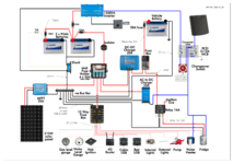
Latest update:
Added RCCB on output of Inverter
Clarified Consumer unit
I haven't added a master switch in the consumer unit because I 'think' an RCD is acceptable and I can't see a way to isolate both the incoming mains and inverter output with a single switch.
 

Attachments

  • wiring layout 2.1.png
    wiring layout 2.1.png
    663.1 KB · Views: 89
Last edited:
Just an RCD will be OK on the inverter output as the inverter has overload protection.

Subscribers  do not see these advertisements

 
For best practice shouldn't the Inverter +ve and the midi fuse holder +ve be connected to the +ve post of the first battery. I know it's a schematic but it might be the final installation document. It's how my lithium's are installed.
 
New to this ... 99% makes sense but what is a shunt?
As Lenny HB says. It's called a shunt for historical reasons, the old-style moving needle amp meters had shunt resistors that made a large percentage of the heavy current bypass the mechanism, in other words the main current was 'shunted' past the mechanism. Technically nowadays they should be called sense resistors, but everyone calls them shunts.
 
Lenny HB Thanks for that explanation autorouter Thanks for the ethymology , English is not my first language and Shunt belongs in Thomas the Tank Engine (Never connected the word to the action there)

Seems like a handy (not nescessary, i suppose you can calculate all appliances individual) thing to have

Now again I am always reverting to basic..... My chassis is "black" Negative for both the leaisure and starter battery are connected to the chassis
(Not as elaborate as connecting all negatives to a bus bar ... my transit bus is the bar)

And it would be quite simple to connect the shunt at any stage between the Neg pole of leisure and the chasis?

Subscribers  do not see these advertisements


Join us or log in to post a reply.

To join in you must be a member of MotorhomeFun

Join MotorhomeFun

Join us, it quick and easy!

Log in

Already a member? Log in here.

Latest journal entries

Back
Top