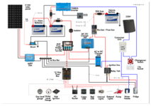
Please critique my wiring diagram.

Joined
Aug 28, 2019
Posts
25
Likes collected
11
Funster No
63,631
MH
Boxer PVC
Exp
ages
This is my curent plan for the wiring for my new van conversion. I'd be grateful for any comments particularly:-
Is the chassis ground the right side of the shunt?
Do I need another isolator before the 12 way fuse box?
Anything else?

Many thanks

Nick
 

Attachments

  • wiring layout.png
    wiring layout.png
    670.8 KB · Views: 1,300
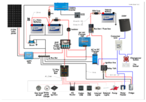
Thanks, thats very helpful. I've ammended the drawing. I still want to connect the Leisure batery to the chassis to avoid running a large ground cable back to the vehicle battery,
 

Attachments

  • wiring layout.png
    wiring layout.png
    670.5 KB · Views: 549
Just cable from your leisure battery negative posts direct to your vehicle chassis.
No. If you have a shunt only the battery negs connect directly to the shunt. On the other neg side of shunt will be the habitation inverter busbar, connections to chargers, etc. Connection to chassis is thus on the opposite side of shunt to the battery.

Unless all neg power passes through the shunt the shunt cannot know correct state of use of batteries.

Revised diagram is correct for neg connections via battery and shunt.

Subscribers  do not see these advertisements

 
No. If you have a shunt only the battery negs connect directly to the shunt. On the other neg side of shunt will be the habitation inverter busbar, connections to chargers, etc. Connection to chassis is thus on the opposite side of shunt to the battery.

Unless all neg power passes through the shunt the shunt cannot know correct state of use of batteries.

Revised diagram is correct for neg connections via battery and shunt.
Yes my bo bo, you are correct, I just nipped out to our van and my cable to chassis is a 25mm2 direct from the non battery side of my shunt. :doh:

I have edited out my previous post so as not to muddy the waters.
 
This is my curent plan for the wiring for my new van conversion. I'd be grateful for any comments particularly:-
Is the chassis ground the right side of the shunt?
Do I need another isolator before the 12 way fuse box?
Anything else?

Many thanks

Nick
Hi,
I am not a van sparky just a user, but if you can upgrade your MPPT to 30a So you are not restricting the charging from solar and maybe do the same for charger
 
Hi,
I am not a van sparky just a user, but if you can upgrade your MPPT to 30a So you are not restricting the charging from solar and maybe do the same for charger
Please explain why think that a Victron 100/20 MPPT is restricting the charging from a 215 watt solar panel, as the max output from a Victron 215w solar panel is 5.75 amps.
 
Last edited:
The 20 sized MPPT solar is adequate for the proposed panel size and has a small amount of headroom. But larger MPPT desired if possibility of a future addition of extra panel. But do make sure cables are good size to avoid a voltage drop.

Agree the battery 12v charger from cab could be larger (depends on alternator size) as 18A would take a very long, many hours, to charge emptied pair of batteries.
 
Please explain why think that a Victron 100/20 MPPT is restricting the charging from a 215 watt solar panel, as the max output from a Victron 215w solar panel is 5.75 amps.
Kannon Fodda has answered your question, as I said I am not a sparky but was advised try to go for biggest capacity MPPT and chargers that you can afford to ensure when upgrading Solar and or battery capacity it is then easy without having to replace existing kit.

Subscribers  do not see these advertisements

 
Thanks, thats very helpful. I've ammended the drawing. I still want to connect the Leisure batery to the chassis to avoid running a large ground cable back to the vehicle battery,
You've changed the diagram, but the comment above is incompatible with the change. Are you on board with KF's comments? You can't also wire the battery negative to the chassis. Ignore the vehicle battery; it looks after itself. Here's another way of looking at it. The shunt must measure all the current returning to the battery; the only way to do this is to have only one connection from the negative posts, direct to the shunt. If you also wire the posts to chassis, some of the return current will go through the shunt, and some will go through the chassis. Not the end of the world, but the shunt will give you the wrong reading and will be useless.

Lots of other things popping up. At first sight:

  1. The shunt requires a tiny amount of power: I wouldn't bother with the 1A fuse to it
  2. The isolator doesn't isolate the inverter, so isn't much use. Ideally, it should disconnect everything from the 12V
  3. The Orion TR12 seems like a waste of money, and adds complexity. My CTEK MPPT costs about the same, and does everything the Orion does as well (I think), and also trickle charges the starter battery when the leisure battery is full. Tip: Victron stuff is expensive, and not necessarily that good
  4. Why have you got a separate AC-DC charger? Doesn't your inverter do that as well?
  5. I've got a bad feeling about your consumer unit wiring. What's the changeover switch for? The inverter has (or should have) relays for changeover. You also need to put the RCCBs between the 230V output on the inverter and the sockets
  6. Are those lead acid batteries? Make sure everything is specced for Lithium. Be careful when buying Victron kit: their stuff may only support their own Lithium batteries, which isn't good
 
Looks good to me in second attachment. Few points I would do diferent.
-B2B at least 30A as already mentioned, with dedicated negative conductor for feed in,
-switch before the midi distribution unnecessary as you introduce extra connection points, and extra resistance, voltage drop etc.
-re size the 2 200A fuses, unless they are T class rated; the 1200va inverter with all the overload, will never exceed 150A, and normal operation 120A at max load;
-feeding the midi’s a 100-125A is more than adequate
 
You've changed the diagram, but the comment above is incompatible with the change. Are you on board with KF's comments? You can't also wire the battery negative to the chassis. Ignore the vehicle battery; it looks after itself. Here's another way of looking at it. The shunt must measure all the current returning to the battery; the only way to do this is to have only one connection from the negative posts, direct to the shunt. If you also wire the posts to chassis, some of the return current will go through the shunt, and some will go through the chassis. Not the end of the world, but the shunt will give you the wrong reading and will be useless.

Lots of other things popping up. At first sight:

  1. The shunt requires a tiny amount of power: I wouldn't bother with the 1A fuse to it
  2. The isolator doesn't isolate the inverter, so isn't much use. Ideally, it should disconnect everything from the 12V
  3. The Orion TR12 seems like a waste of money, and adds complexity. My CTEK MPPT costs about the same, and does everything the Orion does as well (I think), and also trickle charges the starter battery when the leisure battery is full. Tip: Victron stuff is expensive, and not necessarily that good
  4. Why have you got a separate AC-DC charger? Doesn't your inverter do that as well?
  5. I've got a bad feeling about your consumer unit wiring. What's the changeover switch for? The inverter has (or should have) relays for changeover. You also need to put the RCCBs between the 230V output on the inverter and the sockets
  6. Are those lead acid batteries? Make sure everything is specced for Lithium. Be careful when buying Victron kit: their stuff may only support their own Lithium batteries, which isn't good
Can I ask you why you would think an invertor can replace a Ac-Dc charger? The invertor is used to convert 12v to 230v, so when on 240v EHU then the invertor is usually switched off and not therefore would not reverse its current and process from 240v to 12v.

Also Victron gear is used by some of the best installers across the globe both professionally and self builders , what basis do you use to say it’s not good and only supports their own batteries? I have Victron gear and it works with my non Victron batteries.
 
You've changed the diagram, but the comment above is incompatible with the change. Are you on board with KF's comments? You can't also wire the battery negative to the chassis. Ignore the vehicle battery; it looks after itself. Here's another way of looking at it. The shunt must measure all the current returning to the battery; the only way to do this is to have only one connection from the negative posts, direct to the shunt. If you also wire the posts to chassis, some of the return current will go through the shunt, and some will go through the chassis. Not the end of the world, but the shunt will give you the wrong reading and will be useless.

Lots of other things popping up. At first sight:

  1. The shunt requires a tiny amount of power: I wouldn't bother with the 1A fuse to it
  2. The isolator doesn't isolate the inverter, so isn't much use. Ideally, it should disconnect everything from the 12V
  3. The Orion TR12 seems like a waste of money, and adds complexity. My CTEK MPPT costs about the same, and does everything the Orion does as well (I think), and also trickle charges the starter battery when the leisure battery is full. Tip: Victron stuff is expensive, and not necessarily that good
  4. Why have you got a separate AC-DC charger? Doesn't your inverter do that as well?
  5. I've got a bad feeling about your consumer unit wiring. What's the changeover switch for? The inverter has (or should have) relays for changeover. You also need to put the RCCBs between the 230V output on the inverter and the sockets
  6. Are those lead acid batteries? Make sure everything is specced for Lithium. Be careful when buying Victron kit: their stuff may only support their own Lithium batteries, which isn't good
In second picture the chassis is going trough the shunt, the inverter it’s a Phoenix stand alone. So he needs mains charger and swich over.
 
I would put a 200A fuse in both ends of the + lead between the batteries if they are not next to each other.
I am a bit obsessive about fuses after burning out a thin wire which shorted and was not fused.

Subscribers  do not see these advertisements

 
Thanks for all the comments
You've changed the diagram, but the comment above is incompatible with the change. Are you on board with KF's comments? You can't also wire the battery negative to the chassis. Ignore the vehicle battery; it looks after itself. Here's another way of looking at it. The shunt must measure all the current returning to the battery; the only way to do this is to have only one connection from the negative posts, direct to the shunt. If you also wire the posts to chassis, some of the return current will go through the shunt, and some will go through the chassis. Not the end of the world, but the shunt will give you the wrong reading and will be useless.
Sounds like I need an earth cable from the DC charger to the vehicle battery and to keep the whole leisure set-up floating.

Lots of other things popping up. At first sight:

  1. The shunt requires a tiny amount of power: I wouldn't bother with the 1A fuse to it
I've been lackadaisical about fuses in the past and had afew near misses so am being extra cautious this time.

  1. The isolator doesn't isolate the inverter, so isn't much use. Ideally, it should disconnect everything from the 12V
Point taken but it has an on/off switch
  1. The Orion TR12 seems like a waste of money, and adds complexity. My CTEK MPPT costs about the same, and does everything the Orion does as well (I think), and also trickle charges the starter battery when the leisure battery is full. Tip: Victron stuff is expensive, and not necessarily that good
I'm not committed to Victron stuff but have used it before with no problems. Trickle charging the vehicle battery seems like a good bonus though I have had a Ctek charger die on me so there's that.
  1. Why have you got a separate AC-DC charger? Doesn't your inverter do that as well?
I already have the inverter from a previous project and it doesn't to charging as well.
  1. I've got a bad feeling about your consumer unit wiring. What's the changeover switch for? The inverter has (or should have) relays for changeover. You also need to put the RCCBs between the 230V output on the inverter and the sockets
See previous comment re inverter. Will investigate adding RCCBs, thanks.
  1. Are those lead acid batteries? Make sure everything is specced for Lithium. Be careful when buying Victron kit: their stuff may only support their own Lithium batteries, which isn't good
Good point, thanks.
 
The on/off switch on an inverter does not usually actually break the 12v circuit. Just need to look at them to see they are not capable of switching 200A.
 
My two penneth, not normal to have a direct ground to the leisure for the B2B to work you just need a connection from the neg busbar to the neg on the starter battery yes I know this effectively connects the leisure battery to the chassis.
One small mod I'd do is the lighting circuit, wise to have at least two lighting circuits so if a faulty lamp takes out the fuse you are not left in the dark.
 
Please explain why think that a Victron 100/20 MPPT is restricting the charging from a 215 watt solar panel, as the max output from a Victron 215w solar panel is 5.75 amps.
Quoted spec for the Victron 215w panel is 14.6 amps. Still not enough to trouble the 100/20 MPPT though.
 
Looks good to me in second attachment. Few points I would do diferent.
-B2B at least 30A as already mentioned, with dedicated negative conductor for feed in,
-switch before the midi distribution unnecessary as you introduce extra connection points, and extra resistance, voltage drop etc.
-re size the 2 200A fuses, unless they are T class rated; the 1200va inverter with all the overload, will never exceed 150A, and normal operation 120A at max load;
-feeding the midi’s a 100-125A is more than adequate
Looks like I will need to run the 25mm cable to the vehicle battery and that's another vote for a larger B2B chager. Will investigate reducing fuse sizes, thanks.

Subscribers  do not see these advertisements

 
Quoted spec for the Victron 215w panel is 14.6 amps. Still not enough to trouble the 100/20 MPPT though.
But could be useless if you fit additional panels as you will not be able to harvest all the power from the solar panels in summer.
 
Got the output figure from this Product Description

Or are we talking about a different panel ?
Op's diagram shows Victron gear for all major devices and Victron do a 215w solar panel then my assumption was the solar panel would also be Victron, which seemed logical to me. (y)

Edit : I see that your quoted specs are from Alpha Batteries, not Victron.

Subscribers  do not see these advertisements

 
nicknoxx

Could I ask which, app/software you have used to produce your wiring diagram in your opening post?
 
Someone correct me if I’m wrong…….as I’m sure someone will. 🙄

But the small Vbat+ lead that you have shown with the 1a fuse in, should actually connect to the Vehicle battery +

Its not there to ’power‘ the shunt as such, it’s there more as a signal back from the vehicle battery so the app can show the vehicle battery voltage, as shown on the demo screen shot below.

748E67D2-7BA6-4E40-A3AF-864602BB0616.jpeg


Unless you purchase the optional temperature cable and change the setting to to monitor the temp of which ever battery you connect it to.
 
Last edited:
Someone correct me if I’m wrong…….as I’m sure someone will. 🙄

But the small Vbat+ lead that you have shown with the 1a fuse in, should actually connect to the Vehicle battery +

Its not there to ’power‘ the shunt as such, it’s there more as a signal back from the vehicle battery so the app can show the vehicle battery voltage, as shown on the demo screen shot below.

View attachment 697525

Unless you purchase the optional temperature cable and change the setting to to monitor the temp of which ever battery you connect it to.
No the Victon smartshunts need a minute power to enable the computational thingy that shows the battery capacity and such like. So there is a small power feed from the leisure positive.

Added leads can do the temp monitor or cab battery.
 
No the Victon smartshunts need a minute power to enable the computational thingy that shows the battery capacity and such like. So there is a small power feed from the leisure positive.

Added leads can do the temp monitor or cab battery.
Guess it was the Aux that went to the starter battery then………it’s been fitted for a few years now and I’ve never looked at it since I did it. 👍🏼

Subscribers  do not see these advertisements


Join us or log in to post a reply.

To join in you must be a member of MotorhomeFun

Join MotorhomeFun

Join us, it quick and easy!

Log in

Already a member? Log in here.

Latest journal entries

Back
Top