- Dec 2, 2019
- 5,041
- 11,276
- Funster No
- 67,140
- MH
- Rapido 7065+
- Exp
- Broken most bits now
Could you just extend the existing on/off switch wires to a new switch mounted on the panel you want to use?

Follow along with the video below to see how to install our site as a web app on your home screen.
Note: This feature may not be available in some browsers.
i could if i knew which wires were the correct ones. i actually cut the wires that i though were the ones, and soldered a new switch wire - but they werent the correct ones, and im struggling to find the correct onesCould you just extend the existing on/off switch wires to a new switch mounted on the panel you want to use?
yes - look at my first post in this thread and it shows you what i have !Does the inverter have an on/off switch? I don't fully understand the problem - are you trying to identify the wires from that switch?
I used to make and sell an "inverter remote control" kit that could be fitted to any inverter without having to start taking the covers off and getting the soldering iron outthanks, i know that is one option, but i just wanted a simple (small) unobtrusive switch that fitted in with the existing switches in the motorhome already.
")
In that case unsolder the switch & extend its connections?yes - look at my first post in this thread and it shows you what i have !
If only I could !!In that case unsolder the switch & extend its connections?
Like this one?I used to make and sell an "inverter remote control" kit that could be fitted to any inverter without having to start taking the covers off and getting the soldering iron out
I don't do them anymore but basically what you do is get a Power relay (large enough to suit the Inverter, so maybe a 100 or 200A version?), fit that in series on the 12V+ DC line, then you run a lead to a switch located where you want it to turn the relay on and off. Buy a suitable switch that blends in with the existing switches (I used to use the CBE style mounts as they are very common on British and some continental Motorhomes). Job Done.
Better than butchering the inverter (which would also void the warranty when (not if, but when in most cases with inverters) it breaks and save having to mess around again with the replacement inverter)

Well, that one is a little odd - I don't know why it is labelled "2.4W"? That would have to be a tiny voltage for a 200A relay to make sense (If you do the maths, 200A at 12V is 2400W. Maybe "2.4W" should be "2.4KW"? or maybe they mean "24V"? I would not get that due to the confusing labelling.Like this one?
12V 200A Car Truck Auto Automotive Relays 200 AMP SPST ON/Off Relay 4 Pin 4P | eBay
Heavy duty make or break (on/off) relay. Ideal for universal 12V applications. Color: black.www.ebay.co.uk
Your suggestion seems like a very simple solution that even I could do lol!
You could! Cheap iron, heat each switch connection in turn whilst gently pulling.If only I could !!
I can't dismantle everything to get at it !!You could! Cheap iron, heat each switch connection in turn whilst gently pulling.
ive ordered the one you suggested, thanksWell, that one is a little odd - I don't know why it is labelled "2.4W"? That would have to be a tiny voltage for a 200A relay to make sense (If you do the maths, 200A at 12V is 2400W. Maybe "2.4W" should be "2.4KW"? or maybe they mean "24V"? I would not get that due to the confusing labelling.
As an example, this one looks identical and the writing on the relay tells you what it will do
View attachment 682152
Go for one with sensible labelling
I used to sell quite a few of these kits to camper and boat owners. Basic wiring is:
=== Heavy (power) Cable; ---- Light (control) Cable;
BAT +ve ==== FUSE ====== RELAY (PIN 30)
RELAY (PIN 87) ========== INVERTER +ve
BAT -ve =============== INVERTER -ve
BAT -ve ------------------------- RELAY (PIN 85)
RELAY PIN 30 --- fuse ---------- SWITCH IN
RELAY PIN 85 ------------------- SWITCH -ve (this is needed for the LED in the switch to work)
RELAY PIN 86 ------------------- SWITCH OUT
This method removes DC power, so it is important if you have been running the inverter on a high load and it has a fan to let it run for a while before switching off.
You could easily incorporate a countdown timer on the Pin 30/Pin 86 control circuit so when you turn the switch off there is a delay before power is disconnected to make it even easier to use if you want to ensure the fan can stay active for a while.
The relay will only draw power when it is on, as you correctly state. If the inverter is on say 20 minutes a day, that is 0.8W/Day draw. Important to compare the correct consumptions.The 2,4w is the consumption of the coil when in energised state, and continue to draw as long as it stays on that position.
Also the switching on/off for the power supply cables will cycle the caps in the inverter every time you swich. That’s why you have a swich on the pcb to maintain the power cables on so the caps are full. On switching with a relay on the 12v power supply, you will always have that surge until the caps charge.
The power drawn by the caps to maintain full state, is tiny in comparison to a relay coil.
Each to their own.
 )
)thanks, but isnt that just to auto change the power supply from EHU to battery? wouldnt it leave the inverter 'switched on' all the time its not on ehu?This is all I did on a couple of previous vans.
30a relay, power in, power out and one to the inverter. It works an absolute treat.
No switches, it just changes over automatically.
View attachment 682882
No, just turn the inverter on when needed.thanks, but isnt that just to auto change the power supply from EHU to battery? wouldnt it leave the inverter 'switched on' all the time its not on ehu?
lol, not sure you have read the whole thread, but that is what the thread is about - being able to isolate/turn off the inverter remotely .....No, just turn the inverter on when needed.
Ahh, sorry.lol, not sure you have read the whole thread, but that is what the thread is about - being able to isolate/turn off the inverter remotely .....
no probs, i cant find the remote for the inverter and would prefer a switch anyway (with led so i wont forget to turn it off) i actually do intend doing what you have done and have already bought the relay! nice to see it laid out so neatly !!!Ahh, sorry.
I just left mine on and used the remote on the panel.
The Auto-switching Transfer Switch works well but be VERY careful you wire it correctly as any mistake will be costly (you don't want to be feeding 240V INTO the Inverter, that's for sureno probs, i cant find the remote for the inverter and would prefer a switch anyway (with led so i wont forget to turn it off) i actually do intend doing what you have done and have already bought the relay! nice to see it laid out so neatly !!!
can you post your wiring diagram for the relay please so i can confirm what i am doing ? thanks
") )
)it's in my SignatureDo you have an online shop?
Arr cheersit's in my Signature
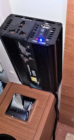
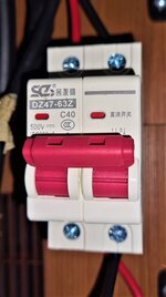
I installed a 300w inverter for my laptop changer (130w), it has a built in switch & led, although I also installed a Main Switch Disconnector just as an added safety measure.I want to set my inverter up via relay, so it automatically becomes 'live' when not on EHU it I also then want to be able to turn the inverter off when not actually being used. I want to fit a switch with a led so I can see when it's on or off.
I identified what I thought were the wires to the switch inside the inverter but they weren't the correct wires.
Can anyone offer some sort of insight please (or offer a suggestion recommendation) where I might be able to get a switch fitted please.
Happy to pay of course!!
View attachment 675115
The switch is connected to the square circuit board. I thought it was one if the red wires, but it isn't, so it might be via the ribbon connection?
You want to avoid having the EHU mains and the inverter connected at the same time, even for a fraction of a second. Mains AC voltage averages 240V, but in fact varies from +340V to -340V 50 times per second. The EHU and inverter mains will not be synchronised, so if you're unlucky there could be 680V between them.I’ve been advised that never plug mains cable in if inverter is ‘ON’ is using the auto change over switch as suggested going to prevent this very situation or do I still need to ensure that inverter is OFF before using mains