Batteries behaving strangely / still reading high voltage

From what I read above there are a lot of people looking too deep into this problem. The OP has confirmed that when some high current appliances are switched on part of the older distribution circuitry suffers low voltage but the battery source voltage does not drop significantly. I get the impression that items on the 'new' distribution wiring do not suffer the same problem.

If the above assumptions are correct then the problem is almost certainly in excessive volt drop in the older circuitry remembering that the -ve (earth) return is just as important as the +ve wires. This could be anywhere but maybe careful consideration of which circuits are affected will reveal a common point.

I would be considering if all the affected items have a common -ve (earth) point, if so I'd find that and check it carefully.

It may be worth connecting a digital meter 'length-ways' along the +ve circuit. By that I mean use the meter on the 20v scale, connect the +ve test lead to the +ve pole of the battery and the -ve test lead a long way down one of the high current affected circuits then apply the offending load. Any significant reading will indicate that there is that amount of volt drop in that circuit. If / when this test shows a problem move the -ve test lead back to half way along the same circuit and test again. At the point that the indicated volt drop disappears you will know that you have passed the fault so back-track until it becomes obvious where the problem is.

I know that sounds complicated and may require a similar test on more than one part of the circuit including the -ve side but once you've got it in your head you will see what I'm getting at. Don't forget if you end up checking the -ve side to reverse the meter test leads (or simply observe numbers on the meter not the fact that some have a -ve sign before them).

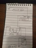
Thanks Rod. I have attached a very basic wiring diagram, not including solar, charge relay or any appliances. As you can see the -ve (earth) for the existing control panel is connected in the engine bay (I never moved it) and the -ve (earth) for the 'new' fuse box is connected to the chassis at the rear of the van (i did this myself, its bolted to the chassis after sandpaper and grease, cleaned it up today).

I didn't realise that the length of the -ve cable could cause a voltage drop but if that is true, do you think this could be the problem? It wouldn't be a major hassle to rewire so everything is earthed to the chassis at the same point.

This may seem like a silly question but if I was to carry out the test you suggested I'd have to rig up a longer cable for the multimeter - presumably I can just cut and crimp the existing probe cable to something longer and attach a croc clip at the end? I assume voltage drop isn't an issue here as it only has to power the multimeter display.
 

Attachments

  • photo_2020-03-01 20.07.23.jpeg
    photo_2020-03-01 20.07.23.jpeg
    86.5 KB · Views: 28
Something is wrong. A voltage drop of 0.4 volts with just a 4A load suggests there is a resistance somewhere. Might be a corroded connection but on such a small load you shouldn't really be able to measure any voltage drop.

As for the batteries, given how you've been using them, discharging them down to about 50%, then they are possibly at the end of their life. It depends on what type of battery they are but if they are a typical lead acid battery then they might be only able to do this about two hundred times. You will got a longer life from gel batteries but they a significantly more expensive to buy although on a VFM basis they can be a good bet. Lithium batteries probably best of all but cost might rule them out for you.

You mentioned a B2B. This is a device which makes the alternator produce more current and charges the batteries much faster than can be done with a split charge relay. One could be an option for you as it will put in as much power with a thirty minute drive as you will get from a two hour or more drive with your current setup.

Hi Peter, they are conventional sealed lead acid batteries.

I'll check out a B2B as all the wiring is already in place, so it wouldn't be a major job.

See my reply above regarding the voltage drop.

Thanks!
 
On my old Adria caravan, I had to replace some full runs of wiring due to the "black death" that can affect DC wiring (negative lead I think ?) The copper wires start to go black and go high resistance which causes a voltage drop.
 
voltage drop of 0.4 volts with just a 4A load suggests there is a resistance somewhere.

Depends on the cable length and size of course, but I don't think that's anything to be concerned about.

I think he's cracked it, the lights are no longer going out so no problemo ?
 
Hi Peter, they are conventional sealed lead acid batteries.

I'll check out a B2B as all the wiring is already in place, so it wouldn't be a major job.

See my reply above regarding the voltage drop.

Thanks!
I doubt the wiring is in place for a B2B unless one was fitted before. They require very thick cables, mine has 25mm2.

Your voltage drop is nearly 4% which shouldn't happen with a tiny 4A load.

Subscribers  do not see these advertisements

 
Thanks Rod. I have attached a very basic wiring diagram, not including solar, charge relay or any appliances. As you can see the -ve (earth) for the existing control panel is connected in the engine bay (I never moved it) and the -ve (earth) for the 'new' fuse box is connected to the chassis at the rear of the van (i did this myself, its bolted to the chassis after sandpaper and grease, cleaned it up today).

I didn't realise that the length of the -ve cable could cause a voltage drop but if that is true, do you think this could be the problem? It wouldn't be a major hassle to rewire so everything is earthed to the chassis at the same point.

This may seem like a silly question but if I was to carry out the test you suggested I'd have to rig up a longer cable for the multimeter - presumably I can just cut and crimp the existing probe cable to something longer and attach a croc clip at the end? I assume voltage drop isn't an issue here as it only has to power the multimeter display.
There is no problem with volt drop on the test leads as long as the connections are good because as you say there is minimal current flowing.

I would keep the test leads unmolested and extend which ever you need with .5mm (or similar) wire BUT do be sure that you insulate the connection to the crock clip as there will be conditions where that lead is at full battery potential so a short to chassis ground will 'fry' the connecting wire!
If you wish to be very safe fit a low current (1Amp or similar) inline fuse in the test lead very close to the connection to the battery +ve test connection.
Those who are used to such testing will see this as OTT but I've seen too many fire damaged write-offs not to always consider safety first!
 
To add to the confusion, your 45w ( 20x2+25) encounters a very high resistance from batt to consumption. As other have mentioned one or more circuits, or even a shared one from where it feeds those lights have a bad connection, or a undersized conductor for its length to feed those loads. Bad crimp, connection corrosion is more likely. You see in excess of 4% drop and a 3.3ohm resistance, on my calc with only 45w load.
As a ref, a 100m solar cable 4mm (thinned cooper) , has a few milliohms. If you distribution panel is fed from batt with only one+cable and one chassis- , then I would run another - cable from batt to distribution panel, at the same size as the existing+ cable. That will bypass the chassis as a conductor and various connections points to it.

Thanks Raul,

That's correct the dist. panel is fed from only those cables. Original wiring. I can remove the original chassis- (in the engine bay) altogether and just wire the dist panel to the -terminal on the batteries. I can run a test cable beforehand to see if it makes a difference.

What gauge cable would you recommend?

On a side note, given that the 12v part of the dist panel. only powers lights, water pump, fan for heater and electric step, what practical impact would a voltage drop have on daily operations (apart from lights being a bit dimmer etc). Presumably when I'm on EHU the voltage drop works the other direction meaning slower charge on the leisure battery?
 
Depends on the cable length and size of course, but I don't think that's anything to be concerned about.

I think he's cracked it, the lights are no longer going out so no problemo ?

Hi Richard I've cracked the original problem but now I want to fix the voltage drop :LOL:. Otherwise it will be like an itch I can't scratch ::bigsmile:
 
Thanks Raul,

That's correct the dist. panel is fed from only those cables. Original wiring. I can remove the original chassis- (in the engine bay) altogether and just wire the dist panel to the -terminal on the batteries. I can run a test cable beforehand to see if it makes a difference.

What gauge cable would you recommend?

On a side note, given that the 12v part of the dist panel. only powers lights, water pump, fan for heater and electric step, what practical impact would a voltage drop have on daily operations (apart from lights being a bit dimmer etc). Presumably when I'm on EHU the voltage drop works the other direction meaning slower charge on the leisure battery?

If you ehu charger runs from that panel, yes the volt drop will-be the other way, and your batt will see a lower voltage than what is set on charger. That will cause insufficient charging voltage and partially charge.
The cable connected to chassis, leave it there for other circuits branching of the panel. You bring a additional neg feed from batt to panel, size the same as existing+ cable. I think you mentioned 10mm. Match that.

Subscribers  do not see these advertisements

 
Hi Richard I've cracked the original problem but now I want to fix the voltage drop :LOL:. Otherwise it will be like an itch I can't scratch ::bigsmile:
This page will help you decide what size cable you need, it includes a voltage drop calculator to help you make sure you stay within the 3-4% limit.
 
On a side note, given that the 12v part of the dist panel. only powers lights, water pump, fan for heater and electric step, what practical impact would a voltage drop have on daily operations
Not much but if it's a bad connection it could get worse, and a bigger voltage drop will consume a wattage and get warm ?

Wattage = volt(drop) x current

So at the minute your cable or bad connection is using 1.6w
 

Join us or log in to post a reply.

To join in you must be a member of MotorhomeFun

Join MotorhomeFun

Join us, it quick and easy!

Log in

Already a member? Log in here.

Latest journal entries

Back
Top