Solar panel on a Hymer 5.4m pop top

Johnra

Free Member
Joined
Sep 27, 2021
Posts
35
Likes collected
31
Location
Suffolk, UK
Funster No
84,497
MH
Hymer 540 Blue Evltn
Exp
I'm a newbie
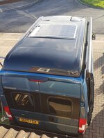
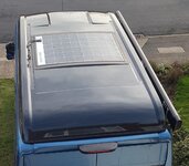
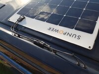
Now testing a home installed 170W Sunpower solar panel on a Blue Evolution 540 pop top. We have only had the van for three months (we are newbies so still learning a great deal) and don't want to mess the van up in any way.

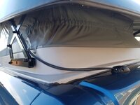
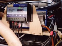
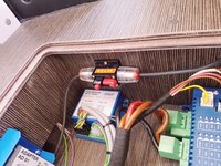
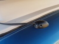
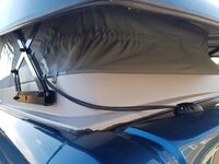
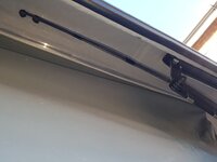
The routing of the cables to the solar panel was 'interesting' - from under the passenger seat where the PV Logic MPPT controller is mounted, via the electrics floor box then behind the loo, over the rear wheel casing, up the nearside rear pillar, out through the steel top (but inside the pop-top edge), up the pantograph support and through the lid to the panel.

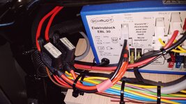
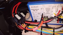
The PV Logic MPPT controller then feeds the the two 95Ah AGM habitation batteries and later the van battery via the solar socket on Schaudt EBL30 van controller. The charging (and configurable) information is shown on an App on the phone giving accurate voltages and currents.

Originally wanted to fit a Victron controller, but they don't make a double output MPPT controller and a friend had a PV Logic controller on his Ayres Rock van.

Hope it will keep all three batteries fully charged over the winter, and also the fridge running with no hook-up in the summer.

So far so good, on a dark wet winter day with no sun it seems to be giving out enough power to raise all the battery voltages to over 13v. Time will tell.

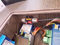
If I have made any mistakes then please point them out. The solar panel has a circuit breaker and the two battery outputs are fused.

The panel is bonded on with Sikaflex around the edge and in the middle.

John
 

Attachments

  • 20211202_130836.jpg
    20211202_130836.jpg
    168.9 KB · Views: 313
  • 20211202_131905.jpg
    20211202_131905.jpg
    470 KB · Views: 309
  • 20211203_075930.jpg
    20211203_075930.jpg
    536.8 KB · Views: 297
  • 20211203_080019.jpg
    20211203_080019.jpg
    416.6 KB · Views: 296
  • 20211203_075857.jpg
    20211203_075857.jpg
    715.8 KB · Views: 319
That looks really good John. I'm a newbie also. Recently bought a 2017 Sunlight T60. Came with a PV Logic 100W panel on the roof and has their PWM controller in one of the high cupboards quite a long way from the battery. Was going to upgrade to the MPPT you have but I've read that MPPTs need to be as close as possible to the battery so not sure. Also mine has the output of the PWM wired directly into the battery positive and negative wires coming out of the back of the EBL 119 unit and not through the unit like you've done. Again not sure why and if one way is any better than the other. Apparently it was fitted this way by Lowdhams when the van was first bought by the PO. What kind of info do you get from the App?
Many thanks, Sean
 
John
one thing to allay fears nay paranoia about charge condition is to get a Battery monitor, that measures voltage and state of charge. These can be got from £25 to £180. I have used both the cheap one bellow

and the expensive BMV712. only changing because the cheap one couldnt change settings for LiFePO4. But Adequate for Lead Acid.
This only measures Voltage and is intended for starter batteries. But is Bluetooth and can give you a prety graph
<Broken link removed>


The Sb is charged by a votronics mppt duo controller
Screenshot_20211202-212654_Battery Monitor.jpg
 
This site contains affiliate links for which MHF may be compensated.
Thanks '1 and only' that looks very useful, will check that out.

Hi Sean,
I am no expert and I have just found today that the 15A solar fuse has gone in the Schaudt EBL 30 when the engine was started.

Am guessing it's a back EMF from the alternator as the solar panel was only giving a couple of Amps. Have disconnected the van battery solar charging link (where I think the back EMF came from ) and the system is working reliably now.

Has anyone else had this issue? It has been working fine on small runs, so it seems like the fuse is not quit big enough. But am reluctant to increase the rating.

So If your PWM is wired to the habitation battery it may have been done for the above reason.

The PV Logic App is very good giving you the solar output and the battery charge information.

PV Logic YouTube video

Best,
John
 
Have routed the outputs from the PV Logic MPPT controller direct to the three AGM batteries (with fuses) and it is all fine now.

The Schaudt EBL30 has been bypassed and this is acceptable according to Schaudt, in fact they suggested it.

The three batteries, two habitation and one van are being gently charged in the winter gloom near to the shortest day with no sun, getting them slightly over 13v during the day.

John

Subscribers  do not see these advertisements

 
Have routed the outputs from the PV Logic MPPT controller direct to the three AGM batteries (with fuses) and it is all fine now.
So to be clear, you have routed the Bat1 output to the leisure batteries, the Bat2 output to the starter battery, and when you start the engine the fuses don't blow?
 
Yes indeed. The inline fuses to both batteries from the controller didn't blow originally, just the 15A solar fuse mounted in the Schaudt EBL30. That is bypassed now and it all seems fine.

I did get an email from Schaudt to say that wiring the outputs of any solar controller direct to the batteries is OK.

John
 
I spoke too soon, the 20A fuses from the PV Logic to the batteries have been blowing. It only happens when I start the van so it must be something to do with an alternator charge surge which goes through the controller from one battery to the other.

The solar charge at the time has been less than 2 Amps.

Solartechnology kindly sent me a replacement PV Logic MPPT controller but the same thing happens.

The sales information says it has diodes to protect this from happening, but whether they are too slow to react and the fuses blow first, I don't know. I have emailed Solar Technology.

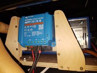
Am considering changing to a Victron 75/15 MPPT Smartcharge controller and a Vanbitz Battery Master. Apparently that is what the main dealer fits now.

Will get there and am very pleased with the Sunpower 170W panel producing 40W on a sunny day in midwinter.

John
 
I spoke too soon, the 20A fuses from the PV Logic to the batteries have been blowing. It only happens when I start the van so it must be something to do with an alternator charge surge which goes through the controller from one battery to the other.

The solar charge at the time has been less than 2 Amps.

Solartechnology kindly sent me a replacement PV Logic MPPT controller but the same thing happens.

The sales information says it has diodes to protect this from happening, but whether they are too slow to react and the fuses blow first, I don't know. I have emailed Solar Technology.
The manual says, when connecting Battery 2 (starter) to the controller after connecting Battery 1 (leisure):

"Please note this battery must be on a separate electrical circuit and
not connected back to ‘Battery 1’ in anyway."

Since the starter and leisure batteries are definitely connected - both negatives are connected to the chassis- then this condition cannot be fulfilled. Charging from the engine alternator (split charge relay or B2B) depends on this common negative connection, so it can't be removed.

I remember seeing something about this somewhere, but I can't find the reference anywhere. Basically it can't be used to charge a starter battery in a vehicle if it's charging the leisure battery too.
Am considering changing to a Victron 75/15 MPPT Smartcharge controller and a Vanbitz Battery Master. Apparently that is what the main dealer fits now.
That looks like a good option. Or a Votronic Duo, which will allow common negative terminals. Or I suppose you could fit a BatteryMaster and keep the existing solar controller charging just the leisure battery.
 
Last edited:
Our Votronic Duo has got a 20 amp fuse in the output. Both starter and leisure batteries are connected and it's never blown 👍

Subscribers  do not see these advertisements

 
Thanks Autorouter, I understood about the common negative for the PV Logic controller, but a friend has an identical setup in a very similar Hymer 5.4m van and it works!

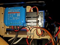
But mine didn't, so have bought a Victron 75/15 and at the moment it is only charging the habitation batteries. It's good to have all the charge information on a phone App, such a shame the Voltronic Duo doesn't do this.

For the charging of the van battery I will need Battery Master, but maybe only feed the van battery from solar when the engine is not running or after the engine has started. Has anyone done this?

John
 

Attachments

  • 20211213_160119.jpg
    20211213_160119.jpg
    305.3 KB · Views: 42
The BatteryMaster is a fit-and-forget solution. It trickle charges the starter battery from the leisure battery. There is a current limiter that prevents high current flow from the leisure battery while the starter motor is cranking. There is a diode (electrical one-way valve) that prevents any back-feeding from the starter battery to the leisure battery.

When the engine is running, the alternator charges the starter battery, and supplies power to charge the leisure battery, either through a split charge relay or a B2B.
 
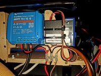
Thanks Autorouter, I plucked up courage and connected the Vanbitz Battery Master, adding a 10A fuse to the van battery just to be very careful. Vanbitz suggested this fuse size. It is working well and after several engine starts and the fuse is fine.

So as Vanbitz advised that they normally wire to the EBL30, I have rewired this way instead of wiring direct to the habitation and van batteries.

On the shortest day with no sun it was charging all three batteries to above 12.8V+

Also used 75mm Bostik flashband tape around the edge of the solar panel to further bond it to the pop top. It has an anodized aluminium foil weatherproof top surface, it sticks very well and saves having to drill the roof.

https://www.screwfix.com/p/bostik-flashband-primer-grey-3-75m-x-75mm/20535

Hope that's the end of the saga!

John
 

Attachments

  • 20211222_143007.jpg
    20211222_143007.jpg
    370.8 KB · Views: 99
  • 20211222_174618.jpg
    20211222_174618.jpg
    456.8 KB · Views: 99
Hi John - arriving late to this thread but wondered if you had considered drilling & screwing the panel to the roof (before obviously going with the gluing/bonding option)?

Thanks,
Joe
 
Hi John - arriving late to this thread but wondered if you had considered drilling & screwing the panel to the roof (before obviously going with the gluing/bonding option)?

Thanks,
Joe

Subscribers  do not see these advertisements

 
Hi John - arriving late to this thread but wondered if you had considered drilling & screwing the panel to the roof (before obviously going with the gluing/bonding option)?

Thanks,
Joe
It's probably been fitted, failed, and got a rigid one by now 🤣

w2f
 
Hi Joe,
No I didn't drill it at all as I was very hesitant about making holes through the pop top into the habitable area. The Bostik flashband is working very well holding it down as well as creating a smooth airflow over the surface. Have driven about a thousand miles with it like that and all is well. It's as cheap as chips so why not buy a roll from Screwfix and see what you think.

By the way, the six fixing holes are filled with black Sikaflex to stop water getting in.

And as for the Mickey taking Richard ::bigsmile:, it was producing 158W on Saturday from a theoretical 170W maximum and that would only be possible if it is at right angles to the sun. Whether it can continue to do this for a couple of years I don't know, but a good start.

John

20211213_144107 (1331 x 998).jpg
 
Many thanks John - the finish looks great by the way!
 
Hi John,

I was wondering if you had any pictures showing the internal routing of the solar panel cabling to the leisure and vehicle batteries? I imagine my Hymer Yosemite has a pretty similar layout to your 540 and hence wondered what cable channels/conduits (if any) you used to get your cables into the van and then discreetly to the batteries?

Many thanks in advance!

Joe
 
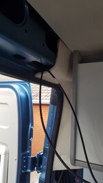
Hi Sam, do you have a pop top? That was a head-scratcher routing the cables along the top edge of the pantograph, but I made some thin aluminium clamps to hold the cables to the scissor framework, then fed the cables into the back of the van via a double entry gland. This meant the rear internal top board had to be removed to get access. See the cables hanging down in photo ...352.

Then I posted them down to the lower section in the corner where a side board by the gas locker was easily removed, next I fished through to the removable access hole in the back of the offside cupboard under the bed. The next bit was the fun bit, getting the cable behind the loo but it is possible if you are patient and poke a wire or thin dowel from the passenger seat corner to join up. It took us a few attempts to get it through but success in the end. Note:- pull out the shower hose first (no need to disconnect) so it doesn't get the solar cables tangled in the pipe loop dangling in that void behind the loo.

Once you are through to the passenger seat corner then down to the electrical box in the floor, I put a circuit breaker in there (now 10A), and across to underneath the seat via a drilled hole in the front board in this box.

If you take your time then it is all straightforward and it did not mean having to remove cupboards as others had done.

From the MPPT controller then round to the front of the seat and into the solar socket in the EBL controller.

Have fun!

John

Subscribers  do not see these advertisements


Attachments

  • 20211203_080019.jpg
    20211203_080019.jpg
    416.6 KB · Views: 90
  • 20211222_174618.jpg
    20211222_174618.jpg
    456.8 KB · Views: 82
  • 20211203_075857.jpg
    20211203_075857.jpg
    715.8 KB · Views: 85
  • 20211130_144352.jpg
    20211130_144352.jpg
    61.8 KB · Views: 85
  • 20211202_131912.jpg
    20211202_131912.jpg
    425.9 KB · Views: 90
  • 20211202_131905.jpg
    20211202_131905.jpg
    470 KB · Views: 85
  • 20211202_131733.jpg
    20211202_131733.jpg
    400.7 KB · Views: 92
  • 20211202_131539.jpg
    20211202_131539.jpg
    533.5 KB · Views: 93
Hi John,

That's fantastic - many thanks indeed! I do have a pop-top yes - just building up the courage now to order the panel and charge controller etc. I fear my knowledge of wiring and circuitry may need an overhaul before embarking on this project though...

All the best,

Joe
 
Hi Sam, do you have a pop top? That was a head-scratcher routing the cables along the top edge of the pantograph, but I made some thin aluminium clamps to hold the cables to the scissor framework, then fed the cables into the back of the van via a double entry gland. This meant the rear internal top board had to be removed to get access. See the cables hanging down in photo ...352.

Then I posted them down to the lower section in the corner where a side board by the gas locker was easily removed, next I fished through to the removable access hole in the back of the offside cupboard under the bed. The next bit was the fun bit, getting the cable behind the loo but it is possible if you are patient and poke a wire or thin dowel from the passenger seat corner to join up. It took us a few attempts to get it through but success in the end. Note:- pull out the shower hose first (no need to disconnect) so it doesn't get the solar cables tangled in the pipe loop dangling in that void behind the loo.

Once you are through to the passenger seat corner then down to the electrical box in the floor, I put a circuit breaker in there (now 10A), and across to underneath the seat via a drilled hole in the front board in this box.

If you take your time then it is all straightforward and it did not mean having to remove cupboards as others had done.

From the MPPT controller then round to the front of the seat and into the solar socket in the EBL controller.

Have fun!

John
Hi John,
this is very helpful. I have a Hymer Grand Canyon S and want to install solar a solar charging system. My questions are:
1. Will a Victron MPPT Controller 100 I 50 too much for the Hymer
2. Am I correct if I understand from your explanation that I connect my solar panels to the MPPT Controller than to the Elektroblock EBL 30 and that is all I need to do. I dont have to do any battery connection?
3. The MPPT controller has 2 cables but the Elektroblock EBL 30 has 3 input slots; how do I go from 2 to 3 wires?
Thanks for to all in advance
 
3. The MPPT controller has 2 cables but the Elektroblock EBL 30 has 3 input slots; how do I go from 2 to 3 wires?
On the 3-way Solar connector, Pin 1 is negative, Pin 3 is the leisure battery positive. Pin 2 (centre pin) goes to the starter battery positive. Some of the pins are labelled with numbers.

The connector is a 3-way MNL (Mate'N'Lok) connector. It comes with separate pins that crimp on the wires. The pins slide into the connector shell, and small barbs lock them in place. Note the connector is not reversible, so get the pins in the right slots.

You also need to put a fuse in the 'Solar' slot, to allow the power to flow to the leisure battery.

Might be worth looking at a dual battery solar controller, like a Votronic Duo, which has an extra battery output that can keep the starter battery topped up.
Thank you for taking time to help
 
1. Will a Victron MPPT Controller 100 I 50 too much for the Hymer
2. Am I correct if I understand from your explanation that I connect my solar panels to the MPPT Controller than to the Elektroblock EBL 30 and that is all I need to do. I dont have to do any battery connection?
The limitation is that the terminals in the EBL front panel connectors are only good for about 15A. That means the solar panels are limited to about 200W. Anything larger needs to go direct to the batteries.

If you go direct to the batteries the EBL can't account for the solar amps so its State of Charge (SOC) percentage indicator will not be accurate. If it has one - many EBLs don't. It's for information only, I don't think it does anything with the SOC readings. The voltage readings will still be accurate.

At the back of the EBL are three heavy-duty wires that provide power from the leisure and starter batteries, and a common negative. This is a good place to connect the solar if it's too much to run through the EBL front. Saves running wires all the way to the batteries.

A Victron MPPT 100/50 is fine up to 600W of solar into 12V batteries. I don't know how much solar panel watts you have, but I suspect not as much as that. It's not the controller you would choose for 200W of panel because it's more expensive than a 75/15 or 100/20, but if you have one already or can get one cheap, it will do the job just the same.

Subscribers  do not see these advertisements

 
This may be of some use - pictures of the cable route from the roof to the inside on my Hymer Grand Canyon S.

The roof is designed with indents for stick on panels.

The cables are drilled through the pop top into the overhang area around the canvas sides and then routed to the rear where there is a velcro joint in the canvas with a cable route into the interior.

I've not followed them down through the interior as yet - I didn't fit the system, but the solar controller is under the front passenger seat. I will be adding another 100 watt panel soon to give me a total of 300 watts but I need to upgrade the controller first.

IMG_6521.JPG


solar wire - 1.jpg
solar wire - 1 (1).jpg


solar wire - 1 (4).jpg

solar wire - 1 (2).jpg

solar wire - 1 (3).jpg
 
This may be of some use - pictures of the cable route from the roof to the inside on my Hymer Grand Canyon S.

The roof is designed with indents for stick on panels.

The cables are drilled through the pop top into the overhang area around the canvas sides and then routed to the rear where there is a velcro joint in the canvas with a cable route into the interior.

I've not followed them down through the interior as yet - I didn't fit the system, but the solar controller is under the front passenger seat. I will be adding another 100 watt panel soon to give me a total of 300 watts but I need to upgrade the controller first.

View attachment 695825

View attachment 695829View attachment 695831

View attachment 695832
View attachment 695833
View attachment 695834
Bit late to this conversation. It would be helpful to understand where the. Able is routed after it goes through the Velcro into the pop top. Thanks
 

Join us or log in to post a reply.

To join in you must be a member of MotorhomeFun

Join MotorhomeFun

Join us, it quick and easy!

Log in

Already a member? Log in here.

Latest journal entries

Back
Top