Shore Power Earth

Red_48

Free Member
Joined
Aug 26, 2018
Posts
55
Likes collected
21
Funster No
55,861
MH
Sprinter CDI313 LWB
Exp
Newbie
What is the correct method of earthing the shore power.

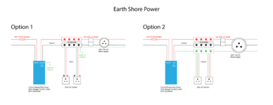
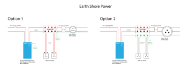
I've mocked up two options that I'm considering, and I'm leaning towards option 2. Many of the marine systems adopt a "floating earth" that does not earth to the chassis.

My DC side is earthed to the chassis on the battery negative terminal.

Much appreciated.
 

Attachments

  • Shore-Power-Earth.png
    Shore-Power-Earth.png
    70.5 KB · Views: 145
Option 2 with chassis earthed ..as per IEE Regs

16.13.2 Requirements for safety

The protective measures of obstacles and placing out of reach are, not surprisingly, precluded by Regulation 721.410.3.5 and, similarly, the protective measures of non-conducting location, earth-free local equipotential bonding are precluded by Regulation 721.410.3.6. The use of the protective measure of electrical separation is not permitted except for shaver socket-outlets, as given in Regulation 721.410.3.3.2.

Regulation 721.411.1 calls for an RCD (see Figure 16.10) where protection by ADS is used (the normal method) with a protective conductor connecting the exposed-conductive-parts of the installation, including socket-outlet protective contacts, with the earthing contact of the caravan inlet plug. The RCD must comply with BS EN 61008-1 or BS EN 61009-1, interrupt all live (line and neutral) conductors and have the characteristics specified in Regulation 415.1.1 (In ≤ 30 mA and operating time ≤ 40 ms at a residual current of 5In).

All extraneous-conductive-parts accessible from within the caravan (or motor caravan) must be bonded with a main protective bonding conductor to the main earthing terminal of the installation in the caravan, as called for in Regulation 721.411.3.1.2. All that will be required, in many cases, will be a ‘main’ bond on to the vehicle chassis.

Regulation 721.43.1 calls for each final circuit to be protected by an overcurrent pro- tective device which disconnects all live (line and neutral) conductors (see Figure 16.10). This will of necessity involve the use of single-pole-and-neutral (SP&N) or double-pole

(DP) circuit-breakers. DP devices will detect overcurrent in both line and neutral and interrupt both on operation, whereas SP&N devices detect only overcurrent in one pole (line) but will disconnect both poles on operation.

Where more than one electrically independent installation is present, each will require its own independent inlet plug, as indicated in Regulation 721.510.3.

Any part of the caravan installation operating at extra-low voltage must comply with the requirements of Section 414 (SELV and PELV) and for d.c. be at one of the standard voltages (12, 24 or 48 V). For a.c., permissible standard voltages are 12, 24, 42 and 48 V.


file uploaded..
 

Attachments

Many Thanks Scot.

I have amended my diagram with option 2 now showing a chassis ground on the earth busbar.

The regulations you quote don't speak to the use of RCBO's as combined RCD and Breaker. Can you see any problems with a combined device? I opted for a double pole RCBO in the hope it will protect against polarity mismatches.
 

Attachments

  • Shore-Power-Earth.png
    Shore-Power-Earth.png
    72.6 KB · Views: 93
Many Thanks Scot.

I have amended my diagram with option 2 now showing a chassis ground on the earth busbar.

The regulations you quote don't speak to the use of RCBO's as combined RCD and Breaker. Can you see any problems with a combined device? I opted for a double pole RCBO in the hope it will protect against polarity mismatches.

personally can't see a problem.. my Hymer has an RCBO fitted .. and yes double pole, as per regs.

I would also advise to only fit non-switched 240v sockets.. same reason .. the switch non a UK 13A socket is only single pole

you won't find any switched 240v sockets on continental vans ..
 
Great tip... Thank You sir

Subscribers  do not see these advertisements

 
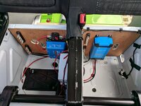
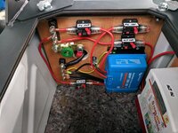
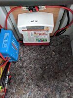
Thanks again Scot. Progress so far...

I'm waiting on a few more bits to arrive so I can start on the shore power side in the adjacent seat base.
 

Attachments

  • IMG_20181005_182544.jpg
    IMG_20181005_182544.jpg
    236.9 KB · Views: 66
  • IMG_20181019_152158.jpg
    IMG_20181019_152158.jpg
    254.3 KB · Views: 69
  • IMG_20181019_152203.jpg
    IMG_20181019_152203.jpg
    175.7 KB · Views: 69

Join us or log in to post a reply.

To join in you must be a member of MotorhomeFun

Join MotorhomeFun

Join us, it quick and easy!

Log in

Already a member? Log in here.

Latest journal entries

Back
Top