Radio will not switch off completely

Joined
Jun 11, 2011
Posts
351
Likes collected
1,156
Location
Derby
Funster No
16,833
MH
Autotrail Cheyenne 840 SE
Exp
2006
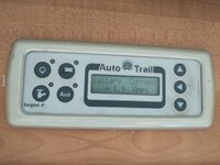
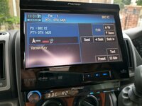
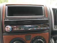
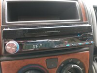
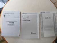
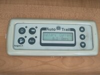
New to me motorhome has an old quality media system fitted, problem I'm having is the off button leaves the facia lit and you can hear a motor running, the draw on the batteries is 1.7amp and when I left the van off hook-up for about 5 days the batteries were very low 😱

Pics of control panel with radio switched off and with it disconnected etc'
Any ideas how to switch it off completely?

Cheers Colin
IMG_20230710_113238021.jpg IMG_20230710_113206282.jpg IMG_20230710_113105383_HDR.jpg IMG_20230710_113132357.jpg IMG_20230710_113143270.jpg IMG_20230710_113315282.jpg
 
Yep I had the same problem. It’s an issue with Pioneer head units.

I ripped mine out as it was hot to the touch and drawing power continuously… I’ve now fitted a Kenwood and I’m running it exclusively from the Hab not Vehicle batteries.

I also fitted an isolation switch ( worth you doing?) so I can completely disconnect if we don’t use the MoHo for extended periods, although the Kenwood, when off, is actually off, so unlikely I will need the switch.
 
The usual reason for this problem is the 12V ACC+ (the red wire typically) should be connected to an Ignition supply and so go on and off with the Ignition. But many MH makers and converters connect this up to a Permanent Supply (usually by just wiring it to the BAT+ (yellow wire typically) so you can listen without the keys in.
Trouble is modern dash radios will only properly turn off when the ACC+ is off. The "On/Off" Button on the radio front is more like a 'standby' button - and a very inefficient standby at that.

I used to make a "Drive/Camping Radio Kit" to get round this problem and have sold hundreds of them over the years to fix this.
 
My Pioneer system was the same when my dealer fitted it. The problem was solved by fitting a switch in the main feed.

Subscribers  do not see these advertisements

 
Last edited:
My Pioneer system was the same when my dealer fitted it. The problem was solved by fitting a switch in th main feed.
Not sure what the "main feed" is, but it is worth mentioning that if you disconnect the 12V BAT+ (yellow) supply to the radio, with many radios you will loose all the presets and configuration immediately. Others may be ok for a short time and the very odd one or two will remember a setup long-term.
It is the Red ACC+line which is the one that needs the tweaking.
 
Thank you all for the prompt replys. :clap2:

As I don't want or need everything this unit gives me I will swap it for something relatively simple so I can set it up ok' And switch it off.

It was nice to have a consensus of opinion as well :giggle:
 
Thank you all for the prompt replys. :clap2:

As I don't want or need everything this unit gives me I will swap it for something relatively simple so I can set it up ok' And switch it off.

It was nice to have a consensus of opinion as well :giggle:
Without dragging this on and on, if you change the head unit for a simplier one, I think you will have exactly the same problem of the dash radio using power even when it is "switched off". Maybe it will use less power, but it will still use power. Swapping it out likely will not achieve what you are hoping.

Seriously, I have lost count of how many people have this kind of problem that I have dealt with. It is especially common on VW Vans as they use canbus wiring, and the typical Canbus-ISO wiring adapters loose the ACC+ supply, whuch results in the installer (DIY AND 'professional') connecting ACC+ to BAT+ (joining Red and Yellow together) when they replace the standard VW radio with an Aftermarket unit like a Kenwood, Pioneer, Sony, etc, etc.
 
I'll just drag it on a bit longer.
Perhaps it's just as well you don't want the functionality of that head unit because they have the habit of the screen failing. Maybe a pioneer badged one will be better and the wiring connecting the screen will be better protected so it does not wear through.
Connect the red and yellow wires from the head unit together through a switch to the current +12v supply. When you pull it out you should find those wires already cut from the loom connector.
"Connect the red and yellow wires from the head unit together through a switch to the current +12v supply." ?? Award for worst advice on the thread :D

I'm outta here :LOL::LOL:

Subscribers  do not see these advertisements

 
Hoovie I obviously misunderstood your previous post because that was how I was reading it.
Yes I know the yellow maintains power to the head but that also uses power as well. On the android head I have just fitted the yellow is the thickest wire in the units loom and must be that size for the current draw. The red wire is just a low power thin switch wire.
Any drain on the hab battery especially over winter is not good unless plenty of solar top-up.
As you can see from all the technical terms I have used I know very little about modern vehicle electronics but my solution worked for me probably won't for everybody.
It may be I misunderstood your description? The way I read it, you were suggesting the Red and Yellow are spliced together, and then that combo is connected to the +12V via a switch. That would give issues in terms of usablility.

Rereading it, were you saying the switch is between Red and Yellow? that is the way to go (y)

Quick resume of wiring for anyone interested (talking aftermarket units for colours) ...
The main power to a head unit is on the Yellow. This supply is used to run the radio, drive the amplifier, and also to maintain the memory of the unit (radio presets on old units, little bit more on newer ones).
The Red wire switches the radio on. It will internally activate some kind of relay to allow the Yellow "power" circuit to run the radio, power the speakers, etc.
When the Red is dead, Yellow is not connected to anything EXCEPT the memory side of the radio. This is a tiny amount of power draw. When the Red is alive, the background draw of a radio even when "off" on the front panel on/off switch can be significant and measured in amps, not tenths, hundreths or millamps. And that draw can kill a battery in a matter of days when stood, even if you have something like an Battery Master or AMT Battery Maintainer.


Below is the wiring diagram I provide with the Drive/Camping Wiring loom and has been used sucessfully for many folk to have their radio work off the Ignition for auto on-off, and bypassing the ignition if they want to listen when parked up. I personally find this dual-control extremely useful.
Drive-Camping-Wiring.png

You will find the great majority of aftermarket radio wiring looms have bullet connectors on the red and yellow wires. This is because some vehicles (usually German ones like VAG and Mercedes) have the ACC+ and BAT+ leads to the radio reversed, and these bullets allow the radio supplies to be easily switched to suit this. My wiring loom takes advantage of that by using those bullets, but using the diagram above it is very easy to recreate this wiring loom yourself if you want to.
Thanks Hoovie when I swap the unit I will follow your diagram and pop a switch in as shown above.

Again thanks to everyone for your input to this thread :giggle:
 

Join us or log in to post a reply.

To join in you must be a member of MotorhomeFun

Join MotorhomeFun

Join us, it quick and easy!

Log in

Already a member? Log in here.

Latest journal entries

Back
Top