New Lifepo4 / Victron instalation CBE ds-300

Joined
Jun 26, 2022
Posts
176
Likes collected
64
Location
Mallorca, Spain
Funster No
89,512
MH
Benimar sport 340
Exp
Benimar sport 340
Hi All,

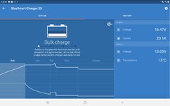
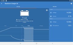
The electrical system in my van is very confusing. I have 3 x 100AH Gel House batteries. For some reason it appears that the 12v side of the van is draining the starter battery. Under the drivers seat there are 2 batteries and from what I can trace, the starter battery gives a supply to charge the auxiliary battery, when the relay allows it. But, it appears that the cables from the solar controller and the cbe ds300 go to the auxiliary battery, not to the house battery bank. As I type this, I have my generator running and my Victron Blue Smart 12v 30A charger, connected to the cables that went from the cbe ds300 to the charge controller. I started with the charger connected to the house batteries and they were full but I was still seeing 11.5v on a USB socket, powered by the cbe ds300. You can see the difference in the screenshots attached. The time difference between these screenshots is 7 minutes, while I changed the charger connections.

I am getting everything ready to convert the system to 600AH Lifepo4 / Victron solar system. My question is, as other wiring is a mess I will be renewing everything, with the correct cable and fuses etc. Obviously I will be removing the original CBE charger and any other unnecessary parts. I want to end up with 1 x 50A 12v supply, from the new house batteries, to the cbe ds300 and allow that to run the original house 12v system.

Is this possible? If yes, which cables need to be removed or added to the cbe ds300? If not, what can be done, to discard as many cables as possible.

I feel that the entire system has been played with by multiple installers and additions to the system.

Any advice / suggestions welcome.
 

Attachments

  • Screenshot_20230106-121150.jpg
    Screenshot_20230106-121150.jpg
    288.2 KB · Views: 71
  • Screenshot_20230106-120443.jpg
    Screenshot_20230106-120443.jpg
    250.3 KB · Views: 66
Does the existing DS300 system, connected to the Aux battery, function correctly? Maybe the only problem is the size of the Aux battery, which means it doesn't last as long as you require it to. It looks as if your 300Ah of gel batteries is not contributing, and the solar isn't going into it either.

One possibility is to keep the DS300 and Aux battery as it is. Then use a small B2B charger, 20A or 30A, to charge the Aux battery from the Gel batteries. This idea of a small B2B to charge one battery from another is not very common, but it's perfectly feasible. It's like wiring a BatteryMaster to trickle-charge the starter battery from the leisure battery, but it's a full-blown 3-stage charger charging the Aux battery from the House batteries. A B2B with a 'D+' connection can have the D+ permanently wired to 12V, so it's always on. It will charge up the Aux battery, then reduce the current to a trickle charge if it's full. If you really want, you can wire a switch into the D+ connection, but you'll probably find you leave it on all the time anyway. While driving, the DS300 split charge relay will charge the Aux battery as before.

For the gel batteries, if you get another B2B, maybe a big 60A one, connected in the usual way to the alternator/starter battery, it can charge the gel batteries while driving. Because the gels are not directly connected to the Aux, there is no need to disable the DS300 split charger, it won't cause any problem to the gels.

You can then get a Victron MPPT controller, and send the solar output to the gels.

So the only connection between the gels and the Aux is a small B2B that keeps the Aux topped up. If the gels ever run out of charge, there's still a reserve left in the Aux battery that will last you a day or so.

The advantage of this setup is that you can easily swap the gels for lithium. You will have ensured that the various chargers for the gels are lithium compatible, so you can just drop them in and switch the settings.

You can then wire an inverter to the lithium setup if you want, without having to worry about the effect on the rest of the habitation circuits.
 
Under the drivers seat there are 2 batteries and from what I can trace, the starter battery gives a supply to charge the auxiliary battery, when the relay allows it. But, it appears that the cables from the solar controller and the cbe ds300 go to the auxiliary battery, not to the house battery bank. As I type this, I have my generator running and my Victron Blue Smart 12v 30A charger, connected to the cables that went from the cbe ds300 to the charge controller. I started with the charger connected to the house batteries and they were full but I was still seeing 11.5v on a USB socket, powered by the cbe ds300.
It looks like you've lost the connection between the gels and the Aux battery. Either a fuse blown or a bad connection. Or even no connection at all if it's badly designed.
 
Hi All,

The electrical system in my van is very confusing. I have 3 x 100AH Gel House batteries. For some reason it appears that the 12v side of the van is draining the starter battery. Under the drivers seat there are 2 batteries and from what I can trace, the starter battery gives a supply to charge the auxiliary battery, when the relay allows it. But, it appears that the cables from the solar controller and the cbe ds300 go to the auxiliary battery, not to the house battery bank. As I type this, I have my generator running and my Victron Blue Smart 12v 30A charger, connected to the cables that went from the cbe ds300 to the charge controller. I started with the charger connected to the house batteries and they were full but I was still seeing 11.5v on a USB socket, powered by the cbe ds300. You can see the difference in the screenshots attached. The time difference between these screenshots is 7 minutes, while I changed the charger connections.

I am getting everything ready to convert the system to 600AH Lifepo4 / Victron solar system. My question is, as other wiring is a mess I will be renewing everything, with the correct cable and fuses etc. Obviously I will be removing the original CBE charger and any other unnecessary parts. I want to end up with 1 x 50A 12v supply, from the new house batteries, to the cbe ds300 and allow that to run the original house 12v system.

Is this possible? If yes, which cables need to be removed or added to the cbe ds300? If not, what can be done, to discard as many cables as possible.

I feel that the entire system has been played with by multiple installers and additions to the system.

Any advice / suggestions welcome.
bit curious on the terms you are using here ...
"For some reason it appears that the 12v side of the van is draining the starter battery". OK, so we have a starter battery.
"the starter battery gives a supply to charge the auxiliary battery, when the relay allows it". And an auxiliary battery.
but ....
" the cbe ds300 go to the auxiliary battery, not to the house battery bank". We have a house battery as well?

What is the difference between the auxiliary battery and the house battery in your van? Have you got two different leisure battery banks? I think some clarification would be useful to help understand what is what in your motorhome?
 
Does the existing DS300 system, connected to the Aux battery, function correctly? Maybe the only problem is the size of the Aux battery, which means it doesn't last as long as you require it to. It looks as if your 300Ah of gel batteries is not contributing, and the solar isn't going into it either.

One possibility is to keep the DS300 and Aux battery as it is. Then use a small B2B charger, 20A or 30A, to charge the Aux battery from the Gel batteries. This idea of a small B2B to charge one battery from another is not very common, but it's perfectly feasible. It's like wiring a BatteryMaster to trickle-charge the starter battery from the leisure battery, but it's a full-blown 3-stage charger charging the Aux battery from the House batteries. A B2B with a 'D+' connection can have the D+ permanently wired to 12V, so it's always on. It will charge up the Aux battery, then reduce the current to a trickle charge if it's full. If you really want, you can wire a switch into the D+ connection, but you'll probably find you leave it on all the time anyway. While driving, the DS300 split charge relay will charge the Aux battery as before.

For the gel batteries, if you get another B2B, maybe a big 60A one, connected in the usual way to the alternator/starter battery, it can charge the gel batteries while driving. Because the gels are not directly connected to the Aux, there is no need to disable the DS300 split charger, it won't cause any problem to the gels.

You can then get a Victron MPPT controller, and send the solar output to the gels.

So the only connection between the gels and the Aux is a small B2B that keeps the Aux topped up. If the gels ever run out of charge, there's still a reserve left in the Aux battery that will last you a day or so.

The advantage of this setup is that you can easily swap the gels for lithium. You will have ensured that the various chargers for the gels are lithium compatible, so you can just drop them in and switch the settings.

You can then wire an inverter to the lithium setup if you want, without having to worry about the effect on the rest of the habitation circuits.
Hi Autorouter, thank you for the complete answer. But, the change over to Lifepo4 is imminent. The 600AH of batteries are fitted, the multiplus 2 12v 3000 has been fitted, the Lynx has been fitted. The victron Smartsolar 150/60 is fitted temporarily, in place of the old Steca 3030, using the original cables and the original solar panels. The Victron smartshunt 1000A is fitted and working. The Cerbo GX is fitted and working, connected to the Smartshunt and the Smartsolar by VE Direct cables and also connected to the Internet through ethernet cable. The Blue Smart 12 - 30 Charger is about to be fitted, as soon as I am sure about the placement of other items. This will take power from the alternator to the new house battery bank.

My Blue sea isolation switches arrived yesterday and I'm not calculating cable Lengths and working out what size cables and fuses that I will need. I have a Blue sea Class T 400A Fuse and holder, ready to fit.

As soon as I can calculate the cable , fuses etc, the switchover will be made.

The biggest problem is, that I live in the van and the change over must be well organised and completed in one day. So I must have e erything fitted and ready to link into the system.

This is why I am concerned about the DS3000 and checking if I must do anything to it or connections to and from it.

Subscribers  do not see these advertisements

 
It looks like you've lost the connection between the gels and the Aux battery. Either a fuse blown or a bad connection. Or even no connection at all if it's badly designed.
Thanks Autorouter, I'll have to take both front seats out and go through it all again. It's the first time I've seen an auxiliary battery fitted in a van, for the van ancillaries. Reading up about it, it was Ford's idea to give more starting power to the Starter battery. So how the DS3000 is draining the Starter battery, I have no idea.

The wiring is a mess and very hard to follow. With my plan, the only wires leaving from under the drivers seat, will be original cables plu the fuse and cabling for the B2B, from the Starter battery to the B2B.
 
Hi Hoovie,

I have the Starter Battery under the drivers seat.
I have an Auxilary Battery" under the same seat.
(Aparently this is standard on some MK7 Ford Transit, twin wheel Chassis Cab Vehicles, used for some European conversions).
The Auxilary Battery gives power to the vehicle ancillaries, to save the Starter Battery from being flattened by abuse of the 12v ancilaries without the engine running.
I have 2 x 100AH Gel House Batteries under the passenger seat.
I have 1 x 100AH Gel House Battery and an inverter under the habitation seat, behind the passenger seat. I presumed those three were the House Battery Bank.

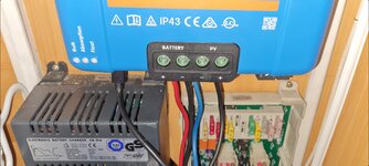
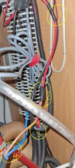
You can see from the photos, The Red and Black cables come out of the SmartSolar "Battery" connections.

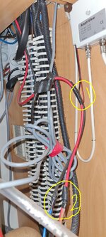
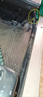
They go down into the boiler cupboard and almost imidiately they gave been spliced into "1". A little further down they are spliced into again "2". Then they go into a conduit "3" and go back yo to the DS3000 House Battery connections.
The splice at point "2" is a twin core (Brown & Blue) cable "4" that then disappears below the false floor, under the boiler. Without removing the water supply, the gas supply and the fan box, then removing the boiler, I can't follow this cable.

the next time I find these cables (I think) is under the drivers seat.

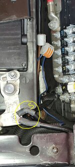
On the side of the drivers seat, there are 2 conduits. Coming out of one of them, is a Blue cable and a Brown cable. You can see them under the battery negative connections "5".
The next photo is a schematic of the battery area. The Brown goes to the Starter Battery + and the Blue is joined and leaves via the other conduit. I can't find where that goes, yet.

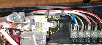
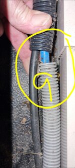
At the back of the drivers seat there are 2 conduits that end up into one and go to the passenger seat. The Blue cable is connected to the main positive bus bar "6" , where the starter cable is connected. The Black cable is connected to the auxilary battery negative. They leave the seat "7" & "8", then they join into one conduit "9" and go to the other seat "10".

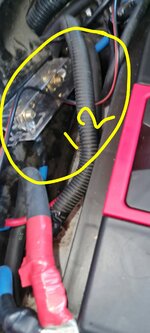
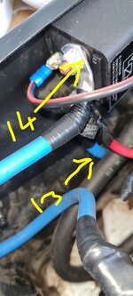
When they enter the passenger seat "11", the blue cable goes through a mega fuse "12" into a VSR "13" and then out "14" to the Positive Starter Battery post "15".

Then cables go to where the third HOUSE battery is and connect to the battery and inverter.

As you can see, its a mess. I want to get my Lifepo4 system ready to connect, with all new cables, properly fused, secured and marked. and then change over in the same day, as I live in the van. The charging side will not be urgent as I will have 600AH and I have a 2.200 generator, to keep me going. But, running a new 12v 50A feed, to the DS 3000, is what I am unsure about.

I will be removing the existing CBE charger and connecting a new HOUSE battery feed to the DS3000.

I need to know if this will cause any problems with the existing 12v HOUSE system. I have no idea how the DS3000 works but I have read about it containing relays for the 3 way fridge and other things. Is there something that knows there is shore power coming in? That will not be there when the shore power goes directly to the Multiplus 2?
 

Attachments

  • Screenshot_20230107_184100_Gallery.jpg
    Screenshot_20230107_184100_Gallery.jpg
    1.3 MB · Views: 159
  • IMG_20230107_184332.jpg
    IMG_20230107_184332.jpg
    348.3 KB · Views: 99
  • IMG_20230107_184533.jpg
    IMG_20230107_184533.jpg
    365.5 KB · Views: 96
  • IMG_20230107_184751.jpg
    IMG_20230107_184751.jpg
    303.8 KB · Views: 94
  • IMG_20230107_184856.jpg
    IMG_20230107_184856.jpg
    1.1 MB · Views: 102
  • IMG_20230107_185007.jpg
    IMG_20230107_185007.jpg
    220.4 KB · Views: 92
  • IMG_20230107_185041.jpg
    IMG_20230107_185041.jpg
    319 KB · Views: 87
  • IMG_20230107_185118.jpg
    IMG_20230107_185118.jpg
    318.6 KB · Views: 86
  • IMG_20230107_185218.jpg
    IMG_20230107_185218.jpg
    320.1 KB · Views: 84
  • IMG_20230107_185340.jpg
    IMG_20230107_185340.jpg
    202.7 KB · Views: 89
  • IMG_20230107_192035.jpg
    IMG_20230107_192035.jpg
    209.2 KB · Views: 90
  • IMG_20230107_185507.jpg
    IMG_20230107_185507.jpg
    209 KB · Views: 132
  • Screenshot_20230107_190538_Gallery.jpg
    Screenshot_20230107_190538_Gallery.jpg
    112.3 KB · Views: 129
I have no idea how the DS3000 works but I have read about it containing relays for the 3 way fridge and other things. Is there something that knows there is shore power coming in? That will not be there when the shore power goes directly to the Multiplus 2?
There is an installation/instruction manual for the DS300 here.
It also contains info on two of the control panels often used with the DS300.

The DS300 has a connection to the positives of the starter battery (B1+) and the leisure battery (B2+). It also has a B- connection that usually goes to the chassis (chassis is called 'masse' in the manual, bad translation).

The DS300 receives a D+ signal from the alternator that indicated the engine is running. This signal has a low power. To avoid overloading it with all the items that use it, the DS300 uses a relay to generate a 'simulated D+ signal' that is fed to everything that requires it, like the fridge, split charge relay, awning light relay step retraction etc.

In addition to the D+ signal, there is also a relay triggered by the D+ that connects the fridge 12V heater element power to the starter battery/alternator when the engine is running.. This is usually about 10A to 15A, depending on the fridge size.

The split charge relay connects the B1+ and B2+ terminals when the engine is running. so that the alternator can directly charge the leisure battery. If you have a B2B for charging the leisure battery, you need to disable this relay, otherwise it shorts out the B2B and renders it ineffective. On the DS300 this can be done by literally cutting away a specific resistor on the circuit board. This is shown in the manual.

There is an indicator for the shore power connection - the existing charger has an extra 12V signal out, to the DS300. I'm pretty sure it's only an indicator on the display panel, I don't think it actually does anything else. So no big deal if you lose it.
 
Last edited:
There is an installation/instruction manual for the DS300 here.
It also contains info on two of the control panels often used with the DS300.

The DS300 has a connection to the positives of the starter battery (B1+) and the leisure battery (B2+). It also has a B- connection that usually goes to the chassis (chassis is called 'masse' in the manual, bad translation).

The DS300 receives a D+ signal from the alternator that indicated the engine is running. This signal has a low power. To avoid overloading it with all the items that use it, the DS300 uses a relay to generate a 'simulated D+ signal' that is fed to everything that requires it, like the fridge, split charge relay, awning light relay step retraction etc.

In addition to the D+ signal, there is also a relay triggered by the D+ that connects the fridge 12V heater element power to the starter battery/alternator when the engine is running.. This is usually about 10A to 15A, depending on the fridge size.

The split charge relay connects the B1+ and B2+ terminals when the engine is running. so that the alternator can directly charge the leisure battery. If you have a B2B for charging the leisure battery, you need to disable this relay, otherwise it shorts out the B2B and renders it ineffective. On the DS300 this can be done by literally cutting away a specific resistor on the circuit board. This is shown in the manual.

There is an indicator for the shore power connection - the existing charger has an extra 12V signal out, to the DS300. I'm pretty sure it's only an indicator on the display panel, I don't think it actually does anything else. So no big deal if you lose it.
Thanks Autorouter.

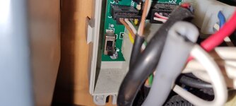
Thanks for the link for the manual. I've read through it but can't find any comment about cutting out a resistor. I've searched and found some information about this. In the 2 images attached, 1 shows the resister to be removed and one is my DS300 and there is a switch in place of the resistor. I'm not sure if there has been a modification made to it before
But I don't see the idea of a switch, without the original resistor being switched into or out of the circuit.

Do you think? If I remove the CBE charger. If I replace the B1+ and B- with a new cable from the new instalation Lynx.

Then bring a new cable from the Starter battery to B1 and B-.

Then a new cable from the alternator charge circuit, to the D+, then the DS300 should continue to work as intended, without the charger.

Are there any other considerations that I should check?
 

Attachments

  • Screenshot_20230108_161955_Adobe Acrobat.jpg
    Screenshot_20230108_161955_Adobe Acrobat.jpg
    241.5 KB · Views: 155
  • 20230108_173737.jpg
    20230108_173737.jpg
    1.8 MB · Views: 153
In the 2 images attached, 1 shows the resister to be removed and one is my DS300 and there is a switch in place of the resistor. I'm not sure if there has been a modification made to it before
The 'resistor' is actually a wire link, not a resistor with a resistance value. So a switch can replace such a wire link.

Automated pick-and-place robots can handle resistors and put them into a circuit board as it is manufactured. They can't handle bits of wire very well. So they use a wire link with a bit added so it handles like a resistor, and call it a 'zero-ohm resistor'. That's what this 'R37' is.
Do you think? If I remove the CBE charger. If I replace the B1+ and B- with a new cable from the new instalation Lynx.
I think that's the B2+ and B-, unless I'm misunderstanding again.

The starter cable to B1+ is used for the fridge 12V element power etc, so yes it needs connecting. Opening that switch will avoid the split charge relay connecting the B2+ and B1+ terminals.

Subscribers  do not see these advertisements

 
The 'resistor' is actually a wire link, not a resistor with a resistance value. So a switch can replace such a wire link.

Automated pick-and-place robots can handle resistors and put them into a circuit board as it is manufactured. They can't handle bits of wire very well. So they use a wire link with a bit added so it handles like a resistor, and call it a 'zero-ohm resistor'. That's what this 'R37' is.

I think that's the B2+ and B-, unless I'm misunderstanding again.

The starter cable to B1+ is used for the fridge 12V element power etc, so yes it needs connecting. Opening that switch will avoid the split charge relay connecting the B2+ and B1+ terminals.
Thanks Autorouter,

I understand what you mean, regarding the link, that's labeled as a resistor. Now the switch makes sense.

Yes, it was a mistake, it should have been:
------"Do you think?
If I remove the CBE charger.
If I replace the B2+ and B- with a new cable from the new instalation Lynx.

Then bring a new cable from the Starter battery to B1 and B-.

Then a new cable from the alternator charge circuit, to the D+.

Then the DS300 should continue to work as intended, without the charger.

Are there any other considerations that I should check.------"

So,
1, with B1+ and B2+ new.
2, Make sure that the switch is set to non continuity.
3, Bring a new cable from the alternator, to the D+ connection.

Is that everything that needs doing?
 
I think so, bearing in mind I haven't seen the whole setup, it sounds like it should work.
Thanks Autorouter,

I will reply to this thread, when I'm ready to swap over to Lifepo4, hopefully it won't be too long now, just in the process of calculating cable sizes and lengths, connectors and fuse blocks / fuses, then order it all.
 
Thanks The1AndOnly,

That looks like a slightly different circuit board to mine but the principle looks the same. Yours has "ON" and "Off" printed on the board, with an image of 2 batteries linked together, between them. Mine has a "0" and a "1" above the image of 2 batteries linked together.
But although yours shows "ON" and "Off", "ON" is at the bottom, mine suggests "1" is equal to your "ON". That suggest that it is connected at the moment.

I was looking for the easiest way to get to the back of the printed circuit board, to check if it was on or off but maybe that's not necessary now.

Thanks...

Subscribers  do not see these advertisements

 
If you can't get to the back of the board, it's possible to find out with a multimeter by measuring a few voltages. When the engine is stopped, the relay will be off, whatever the switch is set to. Measure the starter battery and leisure battery voltages at the B1+ and B2+ terminals. With any luck there will be a measurable difference between them.

Then start the engine. If the switch is set to enable the relay it will now be on. The voltages of B1+ and B2+ will rise, but the important point is, they will both be the same, because the relay is connecting them both. If the switch is set to disable the relay, the voltages at B1 and B2+ will be different.

OK, they may by coincidence be the same, but if you apply a load to one of the batteries, the voltage difference should show up. If the voltages are always the same no matter what load is applied, then the relay is enabled, and is connecting the two batteries.
Thanks Autorouter, that will save a lot of dismantling 😁. It makes complete sense. If the engine is running and I put some load on the house system, I would expect the voltages of both B1 and B2 to be very close but if I change that switch (Disconnecting the battery link), any voltage difference should be more noticeable. If its set up in the way I expect 🤣🤣🤣.

Thank you very much.
 

Join us or log in to post a reply.

To join in you must be a member of MotorhomeFun

Join MotorhomeFun

Join us, it quick and easy!

Log in

Already a member? Log in here.

Latest journal entries

Back
Top