AC from Victron MultiPlus-II 12_3000_120-32 230V

Joined
Jun 26, 2022
Posts
176
Likes collected
64
Location
Mallorca, Spain
Funster No
89,512
MH
Benimar sport 340
Exp
Benimar sport 340
I am instal a new solar system which includes a Victron MultiPlus-II 12_3000_120-32 230V.

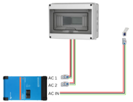
I will be running a new cable from the Shore Power inlet, to the MultiPlus-II, AC IN and there will be a main RCD next to the shore power socket. This will be used on rare occasions but will double as an inlet from my Champion 2200 Watt Inverter Generator -The Mighty Atom - Dual Fuel.

For the 2 AC out, from the MultiPlus-II, I was thinking about a small consumer unit, in the Inverter section, to house 2 x RCD's and 2 x Main MCB's, one of each, for each AC out. Then go to a second consumer unit, in the House section, where each AC circuit will have its own MCB's.
I am planning this way because there is very little room in the Inverter section but I wanted to protect the cables going across the van, to supply the House AC circuits.

Does anyone have any advice on this, please.
 
I would consider using double-pole RCBOs rather than separate RCDs and MCBs. The reason people use separate RCDs and MCBs is that if several MCBs are required, it is more economic to use a single RCD and several MCBs than several RCBOs. However if there is just one cable being protected by the RCB/MCB then an RCBO is better and saves space.

You may have to go to a specialist supplier like CEF to get the double-pole types, they can be difficult to find in the average DIY store - in the UK they only seem to sell single-pole-switched ones.
 
Thanks again autorouter.

So if I have 2 x double-pole RCBOs next to the Inverter. 2 x circuit cables running to the electric cupboard, then seperate trip fuses for each seperate circuit, split between essential AC loads (AC 1) and non essential AC loads (AC 2). In the same consumer unit.

Does that sound right to you?

Does AC1 and AC2 need it's own main shut off, in that consumer unit?
 
AC1 can be run via a double pole swich. AC2 can be directly to a double pole rcbo. It’s only life when plugged in, hence not much use.
AC1 it’s on all the time, and you can still use shore power via AC1 as it’s a pass trough.
 
AC1 can be run via a double pole swich. AC2 can be directly to a double pole rcbo. It’s only life when plugged in, hence not much use.
AC1 it’s on all the time, and you can still use shore power via AC1 as it’s a pass trough.
Are you talking about AC 1 and AC2 from the Multiplus or when the 2 circuits get to the consumer unit in the cupboard? Sorry to be a little confused.

Subscribers  do not see these advertisements

 
In the consumer unit.
 
Thanks Raul,

So it would be, 2 x double-pole RCBOs next to the Inverter. 2 x circuit cables running to the consumer unit iin the electric cupboard, then AC1 through a double pole swich and AC2 through a double pole rcbo.

Then seperate trip fuses for each seperate circuit, split between essential AC loads (AC 1) and non essential AC loads (AC 2). In the same consumer unit.

Is this the idea?
Sorry I had to double read that, why 2x rcbo’s before consumer unit?
AC1 from inverter straight to the consumer unit into a double pole switch. From there out to rcbo’s circuits.
AC2 straight to a double pole rcbo if serves a single circuit for opportunistic loads. If more than one circuit, then copy AC1.
 
It does depend on if you are doing brand new AC electrics, or adding the Multiplus to an existing installation.
Having an RCD before the Multiplus is a useful thing to do. A breaker directly after the Multiplus is also good, and depending on if it is going to an existing CU with an RCD would determine if it needs to be an RCD or not. (Not all motorhome CUs actually have an incoming RCD, such as the last Hymer I looked at).
I tend to use RCBOs rather than either RCDs or MCBs, and on a Multiplus install earlier this week used RCBOs on the AC In and another on the AC Out (it was a 12/1600 so only had one AC Out).

If you take the way Victron setup the EasyPlus integrated CU that shows some useful pointers ....
The Input of the Easyplus goes via a DP MCB
The Output of the Easyplus goes to an RCD, and that then goes to a set of DP MCBs (3 which are EHU/Inverter, and a 4th which is EHU Only).

Ref the 12/3000/120 Multiplus ....
AC1 can be run via a double pole swich. AC2 can be directly to a double pole rcbo. It’s only life when plugged in, hence not much use.
AC1 it’s on all the time, and you can still use shore power via AC1 as it’s a pass trough.
The AC2 Out only working when AC In is active is very handy and far from not much use as it is ideal to connect space heaters to as a key example. Much better than having the Electric Heater bypassing the Multiplus as using AC2 allows the Multiplus to monitor the total incoming load (important when you want to ensure you are not exceeding the supply current).
I use the EHU Only output on my own Easyplus in precisely this way.

PS. It IS possible to have AC2 Out on an Multiplus 12/3000 active WITHOUT AC In being live in fact, despite the general Victron literature saying otherwise, so it might be wise to afford AC2 and AC1 the same type of protection in case you later choose to use AC2 with the inverter output.

Subscribers  do not see these advertisements

 
Sorry I had to double read that, why 2x rcbo’s before consumer unit?
AC1 from inverter straight to the consumer unit into a double pole switch. From there out to rcbo’s circuits.
AC2 straight to a double pole rcbo if serves a single circuit for opportunistic loads. If more than one circuit, then copy AC1.
Thanks Raul, Is it safe to run AC 1 and AC 2, 230V AC cable, from the multiplus un protected, across to the other side of the van and up to the consumer unit.

I was thinking that the 2 RCBO's, on AC1 and AC 2, out of the Multiplus, would protect those 2 cables (Twin and earth) going across to the other side of the van and up to the consumer unit.
 
Thanks foryour comment Hoovie,

I am doing brand new AC electrics. As it is now, there is an existing Heinz 57 varieties instalation and I don't trust it one little bit.

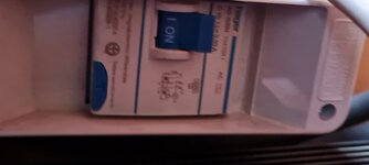
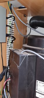
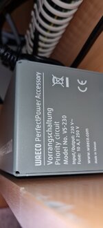
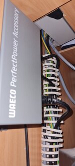
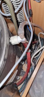
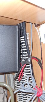
There is an existing shore power socket, leading to an "Eaton Moeller series xPole - PLS4 MCB. PLS4, 2-pole, tripping characteristic: B, rated current In: 13 A, rated switching capacity IEC/EN 60898-1: 4.5 kA" then through about 3 separate AC outlets, to a CBE Battery Charger CBE-516 and to a WAECO PerfectPower Accessory. Vorrangschaltung Priority circuit Model No. VS-230. As you can see from the photos, the word spaghetti comes to mind.

Then there is another area at the front of the van, where the 3rd 100AH gell Battery is ( the other 2 are under the passenger seat). In this area there is an Edecoa 3000W Inverter, A double pole high power battery shut off and A breaker (photo not very clear).

I am having some strange things happening, for example, when my generator is plugged in to the shore power, the fridge does not run on AC but on propane and the engine running, no problems. Also, I am sitting in the dark now because the original 12v distribution panel, a CBE DS3000, is shutting the power off. When this happened tonight, the battery next to the inverter was showing 12.33v from the victron smart battery sense but on a USB socket, piggy backed to the water pump it's showing 9.96v but this will improve tomorrow, after some solar comes in. The solar does charge whatever the water pump is connected to but I must start the engine or run the generator and use my victron bluesmart 12 - 30 charger, direct to the battery next to the inverter, to charge that and I thought the other 2 batteries also.

So, as you can understand, I'm taking it all out and putting in new equipment, mostly victron and lifpo4 batteries.

I've added a design (attached), to show the situation. The Multiplus is about 6m away from the Shore power in. The new consumer unit will be about 3.5m away from the Multiplus. In the new consumer unit, I am thinking to have 3 circuits for AC 1 and 2 higher amp circuits for AC 2. The idea being, that AC 2 will power bigger loads that I might not want to be draining the batteries when the Multiplus assists. I think it's best to have a 16A shore power limit and anything extra from the multiplus. This is what's confusing me, with the breaker Amp ratings.

My biggest concern is to keep the AC and DC safe.
 

Attachments

  • png_20221120_035553_0000.png
    png_20221120_035553_0000.png
    552.9 KB · Views: 57
  • 20220616_091519.jpg
    20220616_091519.jpg
    782.1 KB · Views: 51
  • 20220821_161719 (1).jpg
    20220821_161719 (1).jpg
    200.2 KB · Views: 47
  • 20220731_123616.jpg
    20220731_123616.jpg
    145.9 KB · Views: 46
  • 20221120_015327.jpg
    20221120_015327.jpg
    210.2 KB · Views: 44
  • 20220731_123600.jpg
    20220731_123600.jpg
    204.2 KB · Views: 45
  • 20221120_020105.jpg
    20221120_020105.jpg
    312.2 KB · Views: 42
  • 20221120_020116.jpg
    20221120_020116.jpg
    345.9 KB · Views: 52
Thanks Raul, Is it safe to run AC 1 and AC 2, 230V AC cable, from the multiplus un protected, across to the other side of the van and up to the consumer unit.

I was thinking that the 2 RCBO's, on AC1 and AC 2, out of the Multiplus, would protect those 2 cables (Twin and earth) going across to the other side of the van and up to the consumer unit.
No, my suggestion is valid if CU is next to multi. If you run the distribution across the van, then you will need that extra rcbo’s, right after multi exit.
 
My Victron inverter puts out of phase 115V down both lines so single pole safety devices are useless. The MultiPlus may be different.
 
No, my suggestion is valid if CU is next to multi. If you run the distribution across the van, then you will need that extra rcbo’s, right after multi exit.
Thanks Raul, Maybe I didn't explain it clear enough. What Amp breakers would you suggest?

Subscribers  do not see these advertisements

 
My Victron inverter puts out of phase 115V down both lines so single pole safety devices are useless. The MultiPlus may be different.
Thanks Pausim,

I'm planning on double pole breakers for everything. More so because of 2 separate circuits (AC 1 & AC 2) going into the same consumer unit.
 
Thanks Raul, Maybe I didn't explain it clear enough. What Amp breakers would you suggest?
At the exit 16A, feeding the CU; then smaller per circuit downstream as you distribute to individual circuits.
 
At the exit 16A, feeding the CU; then smaller per circuit downstream as you distribute to individual circuits.
Thank Raul,

I was reading the Multiplus Manuel and found this:

******
• AC-out-1 The AC output cable can be connected directly to the terminal block ‘AC-out’. From left to right: “N” (neutral), “PE” (earth) and “L” (phase) With its PowerAssist feature the Multi can add up to 3 kVA (that is 3000 / 230 = 13 A) to the output during periods of peak power requirement. Together with a maximum input current of 32 A this means that the output can supply up to 32 + 13 = 45 A. An earth leakage circuit breaker and a fuse or circuit breaker rated to support the expected load must be included in series with the output, and cable cross-section must be sized accordingly. ******

If my input from shore power is 16A, shouldn't AC 1 be 16A plus the possible 13A from PowerAssist?

Is AC 2 effected in the same way?
 
If you plan to use it’s full power in pass trough then exit can be as much as 32A. The output assist its 13A nominal plus a bit for overload. The multi overload can be as high as 5-kva.

All the pass trough will be shared accros AC1 and 2.
Add on AC1 power assist of 13A nominal, more like 16A to cover for overload capability as well.

What you powering with all this? I run the hole house of a 5kva with a 32A main breaker.
 
Thanks for that Raul. So I will need a 32A on AC 1 and 32A on AC 2 ??

Subscribers  do not see these advertisements

 
32a on ac1 as you cumulate the pass trough plus power assist.
16a on ac2 as it’s only pass trough without power assist.
 
Thanks Raul, Brilliant, thank you. I wasn't sure about AC 2 but you've confirmed that for me.

For the breakers in the consumer unit. The circuits from AC 1 will be for sockets. The circuits for AC 2 will be for higher power sockets. If I have 3 circuits on AC 1 and 2 circuits on AC 2, what do you think I should limit the breakers at? I know that it depends on the demand but is there a general rule? As everything will not be used at the same time. At the moment, I only turn on the existing Inverter when I use the microwave or the AC TV. But the renovation is ongoing and there will be more demand, as and when I have the lifepo4 batteries and the new panels installed. Things like the fridge would probably be better on AC 1, just in case I run out of propane. So I'm guessing that this will be one of the AC 1 breakers and will be rated at the Amperage needed for that item only but the sockets would need to be higher Amperage and not all on the same circuit.
 
You will have to chose the breakers according to what you going to power up. I guess 10’s will be ok, even 6a breakers for boiler fridge etc. my 16a out feeds 3 circuits: 1 10a sockets kitchen, 1 10a sockets habitation 1 6a boiler.
Make sure the cable is adequate for the breaker ratings. 👍
 
My Victron inverter puts out of phase 115V down both lines so single pole safety devices are useless. The MultiPlus may be different.
That's one of the reasons the regs say that systems in a motorhome should have double-pole safety devices, not single-pole ones like UK domestic circuits.
 
That's one of the reasons the regs say that systems in a motorhome should have double-pole safety devices, not single-pole ones like UK domestic circuits.
Are they actual regulations? or recommendations? I think the latter.

Subscribers  do not see these advertisements

 
The breaker ratings don't have to add up. You can have half a dozen 10A breakers from a 16A main breaker. In this situation it's up to the user to juggle the usage so that the main breaker doesn't trip. It's possible to automate this to some extent, using load-shedding relays. For example, it could switch off the water heater when the toaster is on, and back on when the toast is done. But that's another can of worms...
 
The breaker ratings don't have to add up. You can have half a dozen 10A breakers from a 16A main breaker. In this situation it's up to the user to juggle the usage so that the main breaker doesn't trip. It's possible to automate this to some extent, using load-shedding relays. For example, it could switch off the water heater when the toaster is on, and back on when the toast is done. But that's another can of worms...
Indeed. I mentioned the Easyplus earlier? That has a 16A input with Power Assist capability.
This is how their Consumer is configured....
16A Input Breaker
25A Output RCD (needs to be bigger than Max Input plus PA) with 1 x 16A Breakers + 3 x 10A Breakers

Easyplus CU
by David, on Flickr

I have mine setup so if I am not on EHU, and the Microwave is running, the relay connection to the Water Heater element is disabled to avoid possible Inverter Overload.
 
You will have to chose the breakers according to what you going to power up. I guess 10’s will be ok, even 6a breakers for boiler fridge etc. my 16a out feeds 3 circuits: 1 10a sockets kitchen, 1 10a sockets habitation 1 6a boiler.
Make sure the cable is adequate for the breaker ratings. 👍
Thanks Raul, I appreciate you taking the time to help.t
The breaker ratings don't have to add up. You can have half a dozen 10A breakers from a 16A main breaker. In this situation it's up to the user to juggle the usage so that the main breaker doesn't trip. It's possible to automate this to some extent, using load-shedding relays. For example, it could switch off the water heater when the toaster is on, and back on when the toast is done. But that's another can of worms...
Thanks autorouter,

That's something that I can look into after it's up and running but you have got me thinking 🤔.
 
Could you guys just check the breakers that I've found, please.

I have selected the following but not ordered them yet.

For the PV to MTTP.
IMG_20221124_001618.jpg

1 x Photovoltaic Combiner Box for Solar Panels DC 32A 0-1200V ON-Off Transer Disconnect Switch Miniature Circuit Breaker IP66 Waterproof Isolator (UKPM 32A IP66).

For the Multiplus AC1.
IMG_20221124_001645.jpg

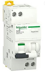
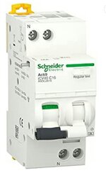
1 x Schneider ACTI 9 iCV40 1PN C 32A 30mA AC RCBO.

For the main Shore Power inlet & For the Multiplus AC2.
IMG_20221124_001715.jpg


2 x Schneider ACTI 9 iCV40 1PN C 16A 30mA AC RCBO.

For the House Consumer Panel. From Multiplus AC1: 1 x 6A & 1 x 10A.

From Multiplus AC2: 1 x 6A & 3 x 10A.
IMG_20221124_001816.jpg

2 x Schneider a9 K01106 – Disyuntor k60 N 1P, 6 A, B, Característica 6 ka.

IMG_20221124_001747.jpg


4 x Schneider 60127 – Disyuntor C60, ul489, 1P, 10 A, D, Característica 240 V AC.

Any suggestions welcome...👍
 

Attachments

  • IMG_20221124_001715.jpg
    IMG_20221124_001715.jpg
    186.6 KB · Views: 27
  • IMG_20221124_001645.jpg
    IMG_20221124_001645.jpg
    185.7 KB · Views: 35

Join us or log in to post a reply.

To join in you must be a member of MotorhomeFun

Join MotorhomeFun

Join us, it quick and easy!

Log in

Already a member? Log in here.

Latest journal entries

Back
Top